目录Table of Contents
Part 1 / 概览Part 1 / Overview
一、规格概览1.1 Specifications
表 1-1 CHAMP 2 竞速飞塔总规格Table 1-1 Overall specifications of the CHAMP 2 racing stack
| 项目Item | CHAMP 2 参数CHAMP 2 Specs |
|---|---|
| 产品名称Product Name | Oxbot Champ 2 竞速飞塔Oxbot Champ 2 Racing Stack |
| 飞控主控FC MCU | STM32H743 |
| 电调主控ESC MCU | ATF421 |
| 飞控固件FC Firmware | Betaflight,目标名称:CHAMP_H743_V2Betaflight, target name: CHAMP_H743_V2 |
| 电调固件ESC Firmware | OX32 |
| 陀螺仪Gyro | ICM42688 / MPU6000,不同版本请以产品标签和固件版本为准。ICM42688 / MPU6000. Please refer to the product label and firmware version for the exact variant. |
| 输入电压Input Voltage | 3-8S LiPo |
| 5V BEC 输出5V BEC Output | 5V / 3.5A |
| 电调持续电流ESC Continuous Current | 每路 60A60A per channel |
| 峰值电流Peak Current | 每路 70A70A per channel |
| 安装孔位Mounting Pattern | 20 x 20mm, M3 |
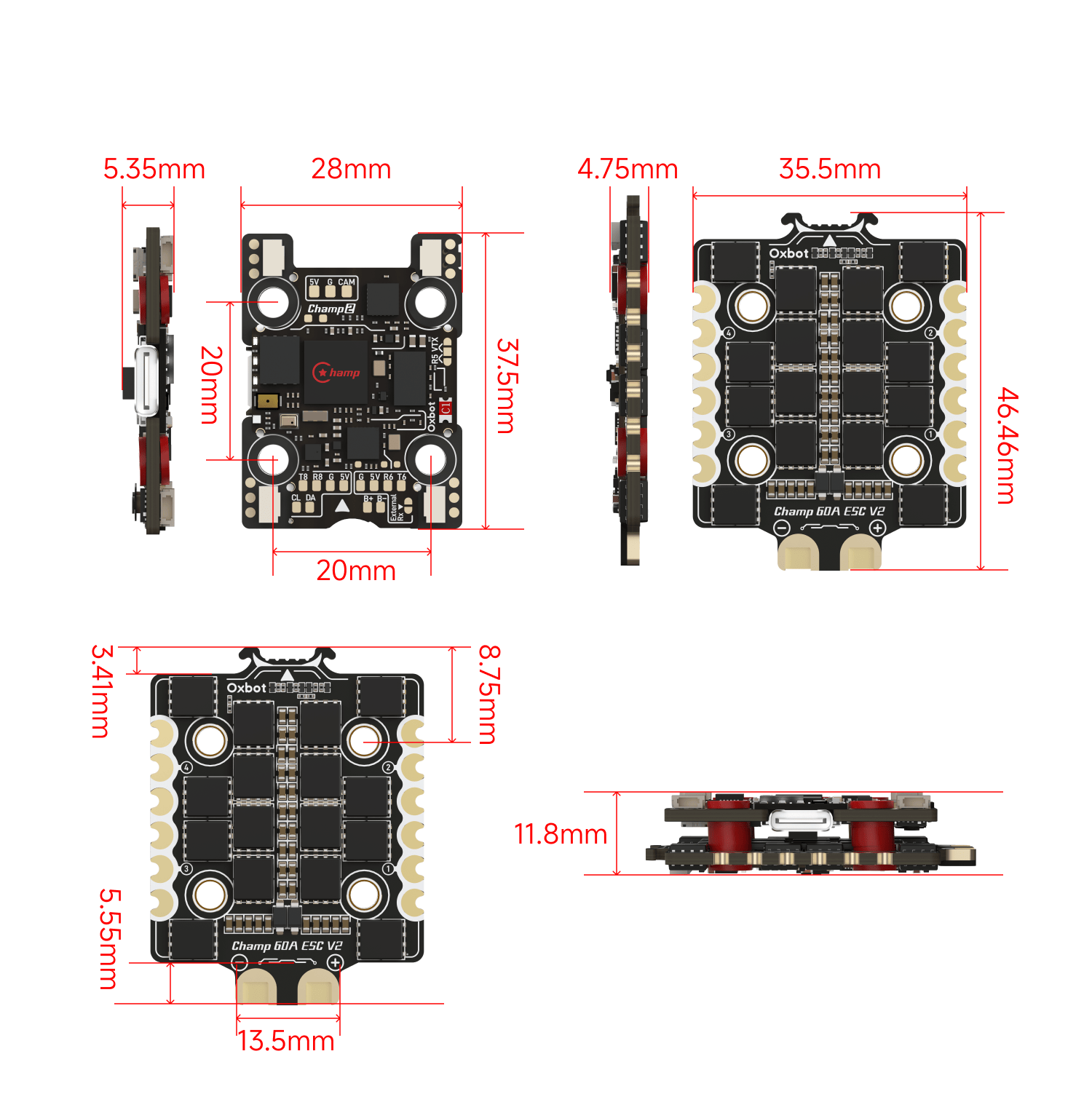
| 尺寸Dimensions | 飞控尺寸:37.6 x 28.3 x 5.35mm 电调尺寸:46.5 x 35.5 x 4.35mmFC dimensions: 37.6 x 28.3 x 5.35mm ESC dimensions: 46.5 x 35.5 x 4.35mm |
| 重量Weight | 飞控:7.8g;电调:16.5g;整套:24.3gFC: 7.8g; ESC: 16.5g; full stack: 24.3g |
二、尺寸标注1.2 Dimensions
三、飞塔安装方式1.3 Stack Installation
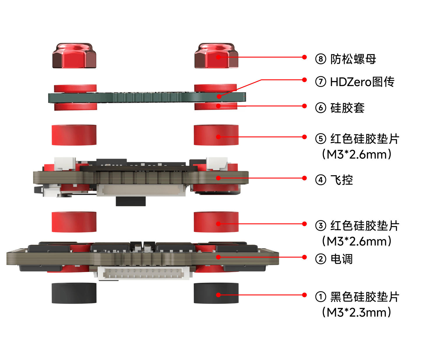
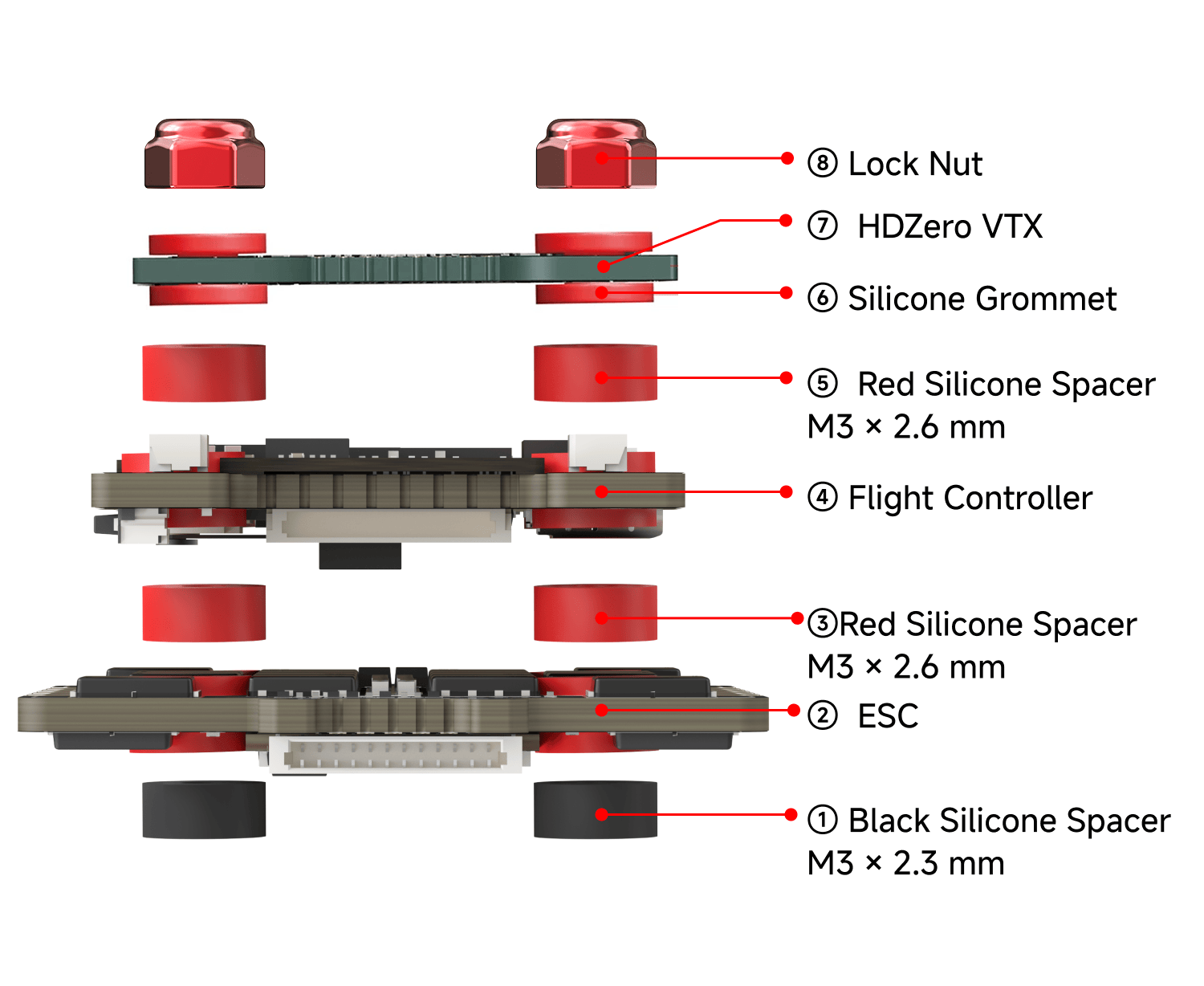
要点提示:Key Notes:
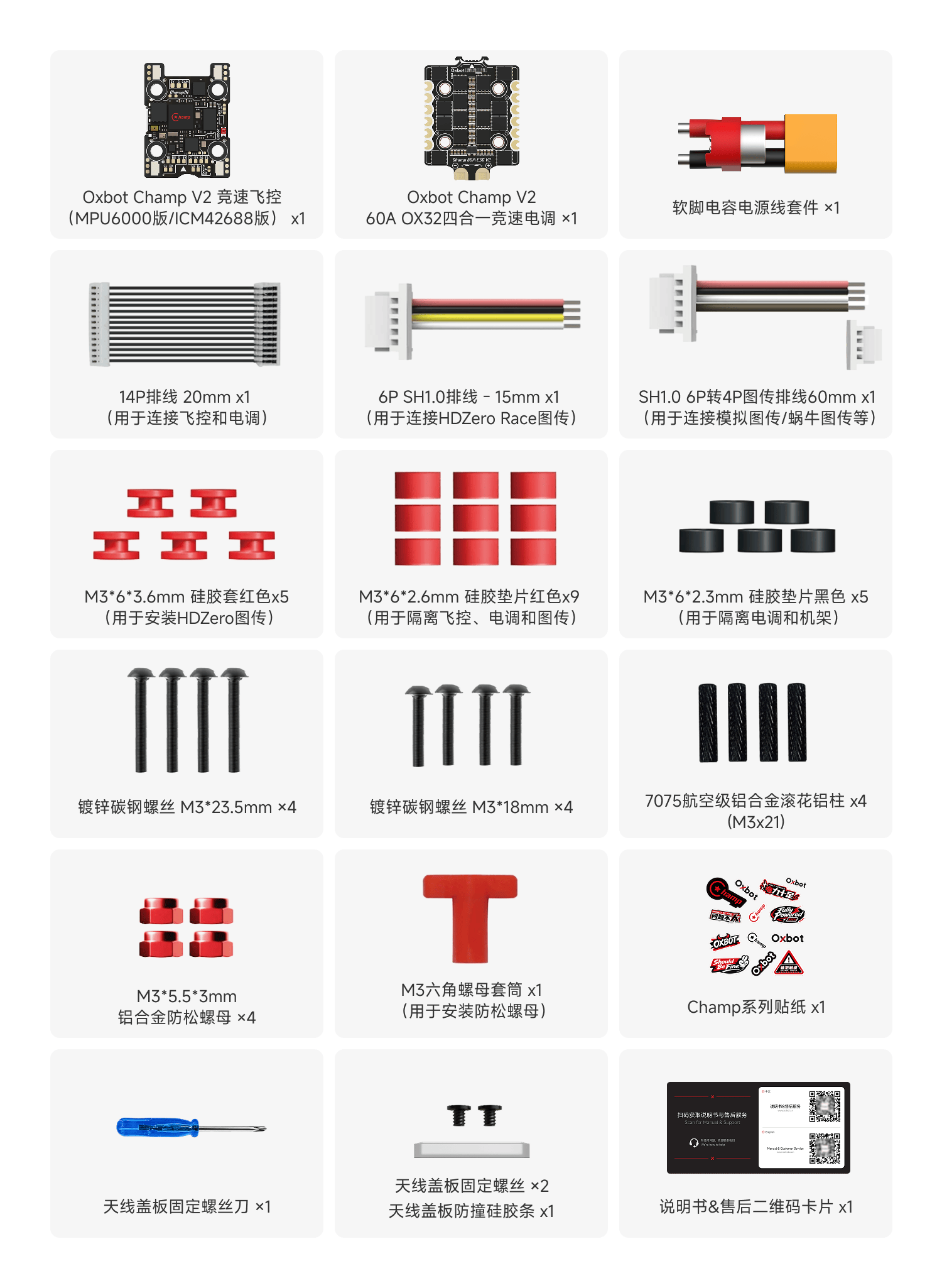
- 强烈建议把 HDZero 图传原先的硅胶套替换为本产品中的硅胶套(如⑥所示),并配合使用本产品中 21mm 高的铝柱,以降低机身高度,获得更优飞行效果。It is strongly recommended to replace the original HDZero silicone grommets with the silicone grommets included in this kit (as shown in step 6), and use the included 21mm aluminum standoffs to reduce stack height and achieve better flight performance.
- 请严格按上图方式安装硅胶垫片,否则可能导致飞塔、图传及机架之间相互接触,造成损坏。Install the silicone spacers exactly as shown above. Incorrect installation may cause contact between the stack, VTX, and frame, which can lead to damage.
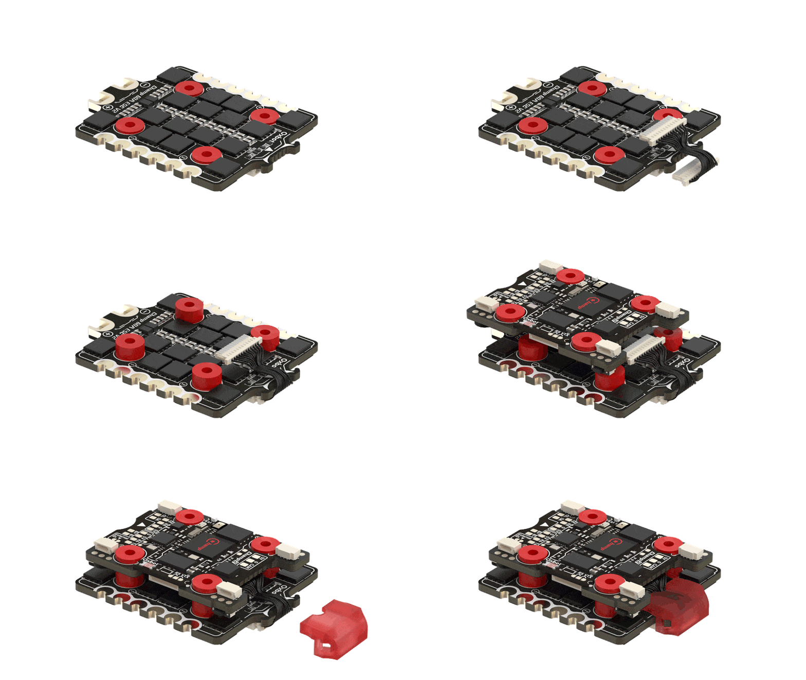
排线保护打印件安装说明Cable Guard Installation
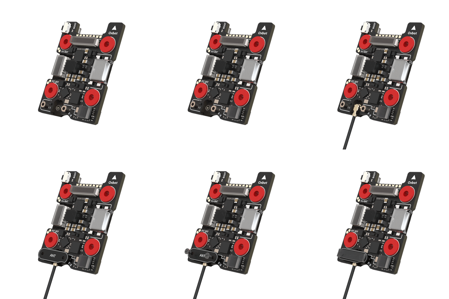
内置接收机天线更换Built-in Receiver Antenna Replacement
更换内置接收机天线可以使用随包螺丝刀卸下天线压板螺丝,取下压板后更换天线。安装时请确认天线接头压紧,并重新锁紧压板,并且将配件中额外配的硅胶垫片安装到飞控上。To replace the built-in receiver antenna, use the included screwdriver to remove the antenna clamp screws, take off the clamp, and replace the antenna. When reinstalling, make sure the antenna connector is fully seated, tighten the clamp again, and install the extra silicone spacer included in the accessory pack onto the FC.
四、飞控与电调连接1.4 FC / ESC Connection
连接方式一:使用排线连接Method 1: connect with the ribbon cable
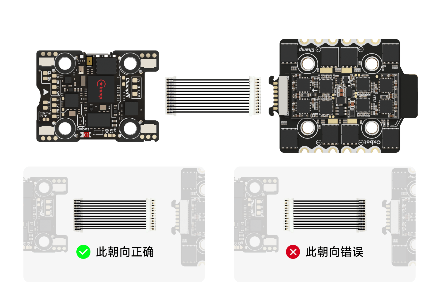
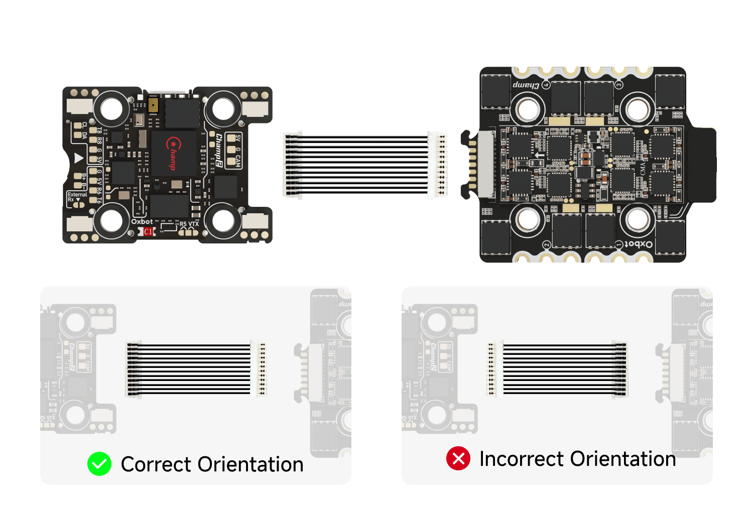
连接方式二:焊接连接Method 2: soldered connection
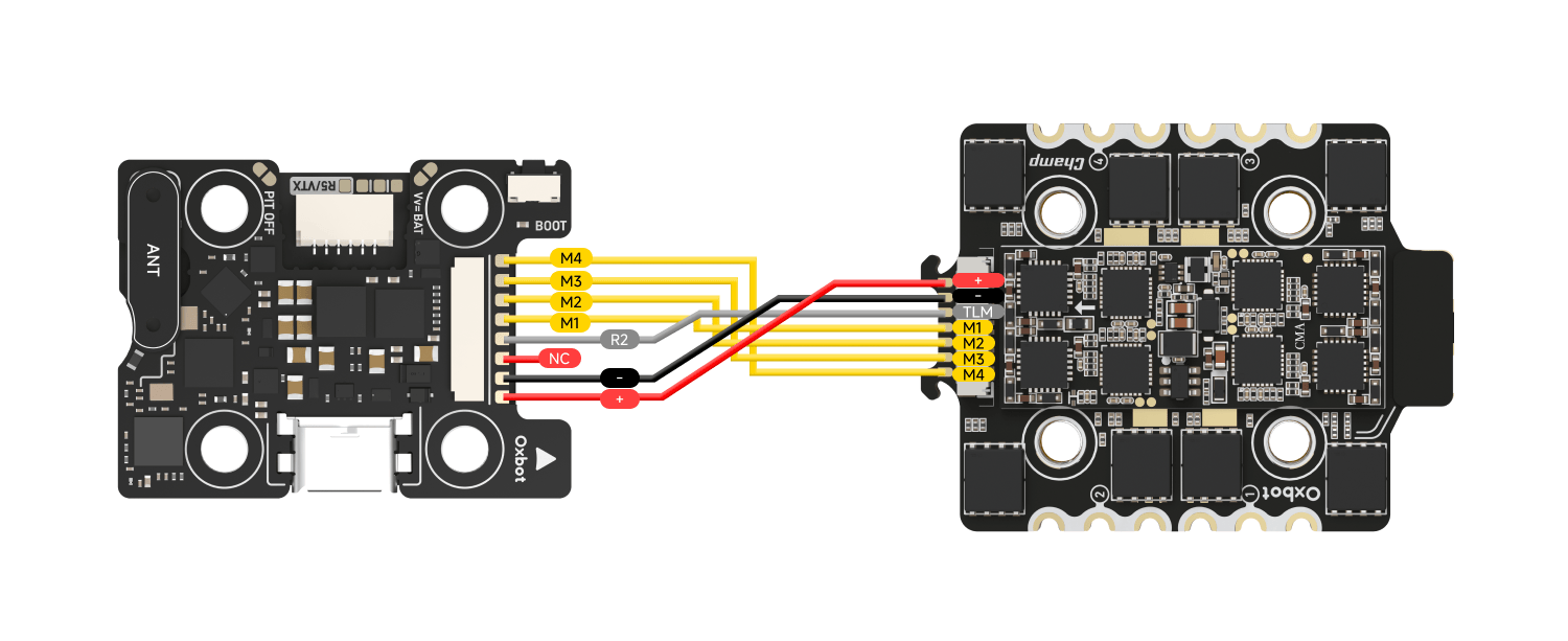
飞控与电调也可通过焊盘焊接连接。推荐优先使用原装排线。若使用焊接方式,请严格按照焊盘定义连接,并在上电前检查短路。The FC and ESC can also be connected by soldering the pads directly. The original ribbon cable is recommended whenever possible. If you choose a soldered connection, follow the pad definition exactly and check for shorts before powering up.
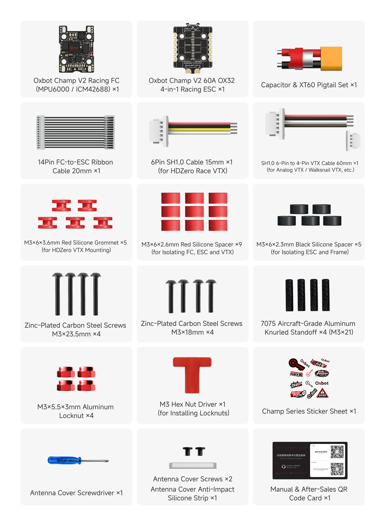
五、包装配件1.5 Accessories
Part 2 / 飞控Part 2 / Flight Controller
一、外观说明2.1 Appearance
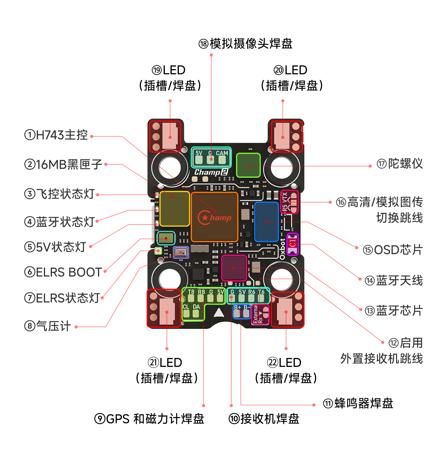
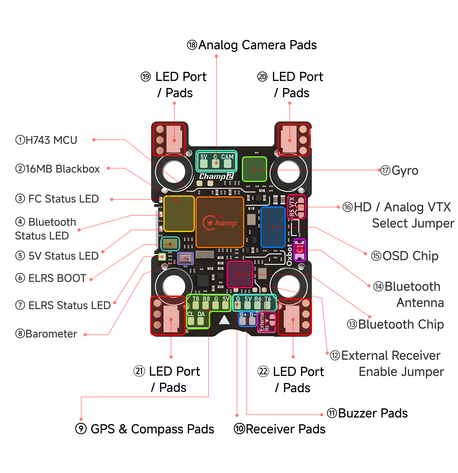
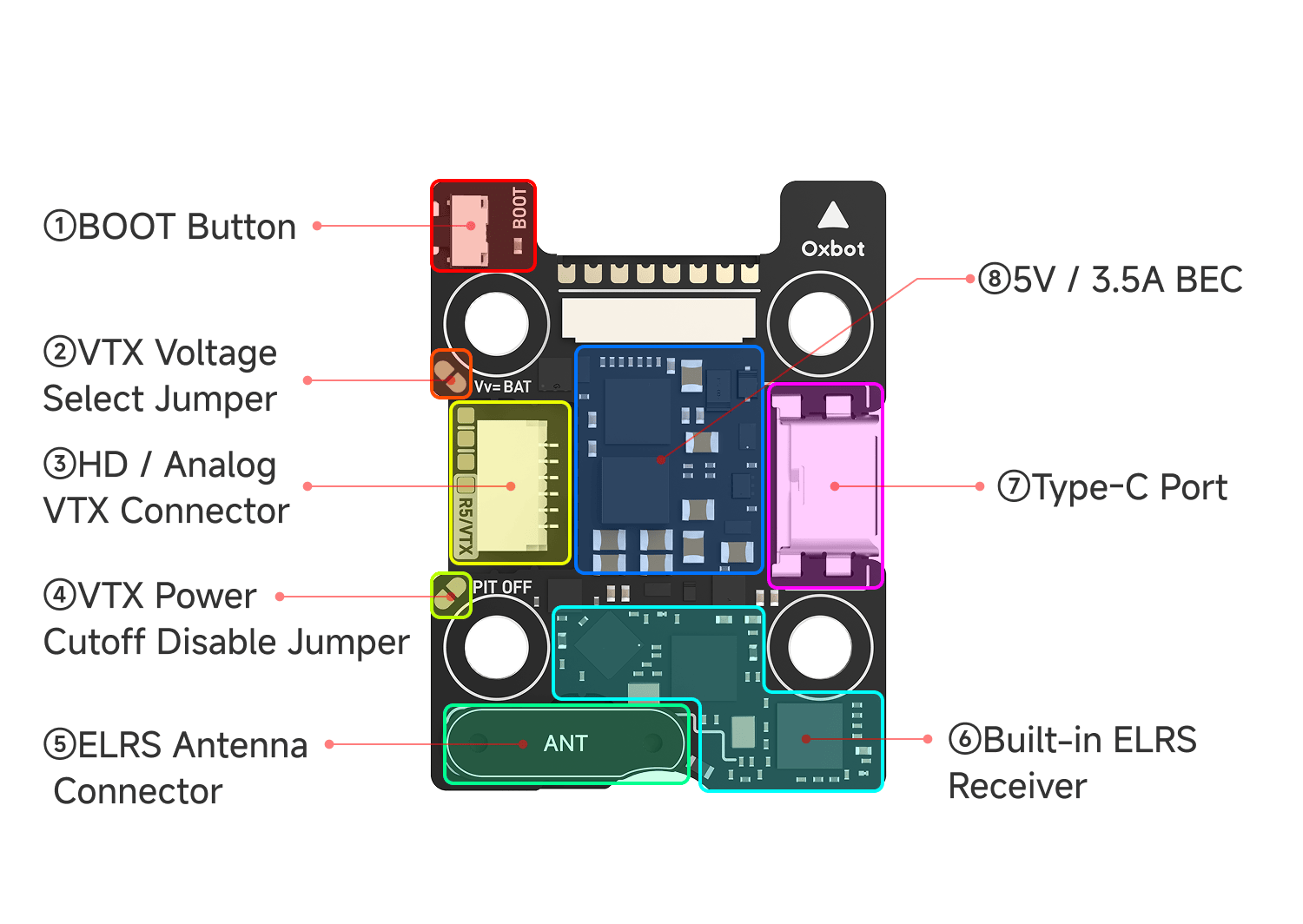
二、状态灯与跳线说明2.2 LEDs & Jumpers
表 2-1 状态灯说明Table 2-1 LED status reference
| 指示灯Indicator | 颜色/状态Color / State | 含义Meaning |
|---|---|---|
| 主控状态灯MCU status LED | 蓝色Blue | 由主控控制,表示飞控状态。Controlled by the FC MCU to indicate controller status. |
| 蓝牙状态灯Bluetooth status LED | 绿色Green | 蓝牙连接成功后常亮。Solid on after a successful Bluetooth connection. |
| 5V状态灯5V status LED | 红色Red | 常亮表示 5V BEC 已正常输出。Solid on indicates the 5V BEC output is working normally. |
| ELRS状态灯ELRS status LED | RGB灯RGB LED | 慢闪:等待遥控器或高频头连接 常亮:已连接遥控器或高频头 绿色呼吸灯:接收机处于 Wi-Fi 模式 连续闪烁两次:接收机处于对频状态 连续闪烁三次:Model Match 不匹配。请检查遥控器/高频头与接收机的 Model Match 设置,确保两端模型 ID 一致,或关闭 Model Match 后重新对频。Slow blink: waiting for the radio transmitter or TX module to connect. Solid on: connected to the radio transmitter or TX module. Green breathing: receiver is in Wi-Fi mode. Double blink: receiver is in bind mode. Triple blink: Model Match mismatch. Check the Model Match setting on both the transmitter / TX module and the receiver, make sure the model ID matches, or disable Model Match and bind again. |
表 2-2 跳线说明Table 2-2 Jumper reference
| 跳线Jumper | 跳线说明Description | 默认状态Default | 示意图Diagram |
|---|---|---|---|
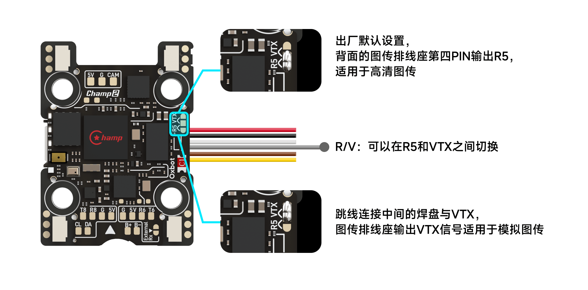
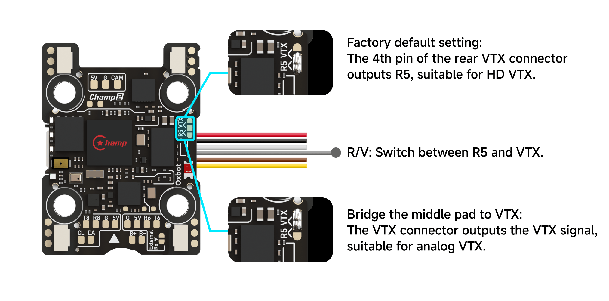
| 高清模拟切换跳线HD / Analog signal jumper | 作用:用于切换背面天空端排线座及对应焊盘第 4 Pin 的信号。 使用场景:使用高清图传时切换到 R5;使用模拟图传时切换到 VTX。 注意:若使用模拟图传但未切换到 VTX,图传控制或 OSD 可能异常。Function: Switches the signal on Pin 4 of the rear air-unit connector and its matching pad. Use case: Set it to R5 for digital HD video systems, or VTX for analog video transmitters. Note: If you use an analog VTX without switching to VTX, VTX control and OSD may not work correctly. | R5(高清图传)R5 (digital HD VTX) | 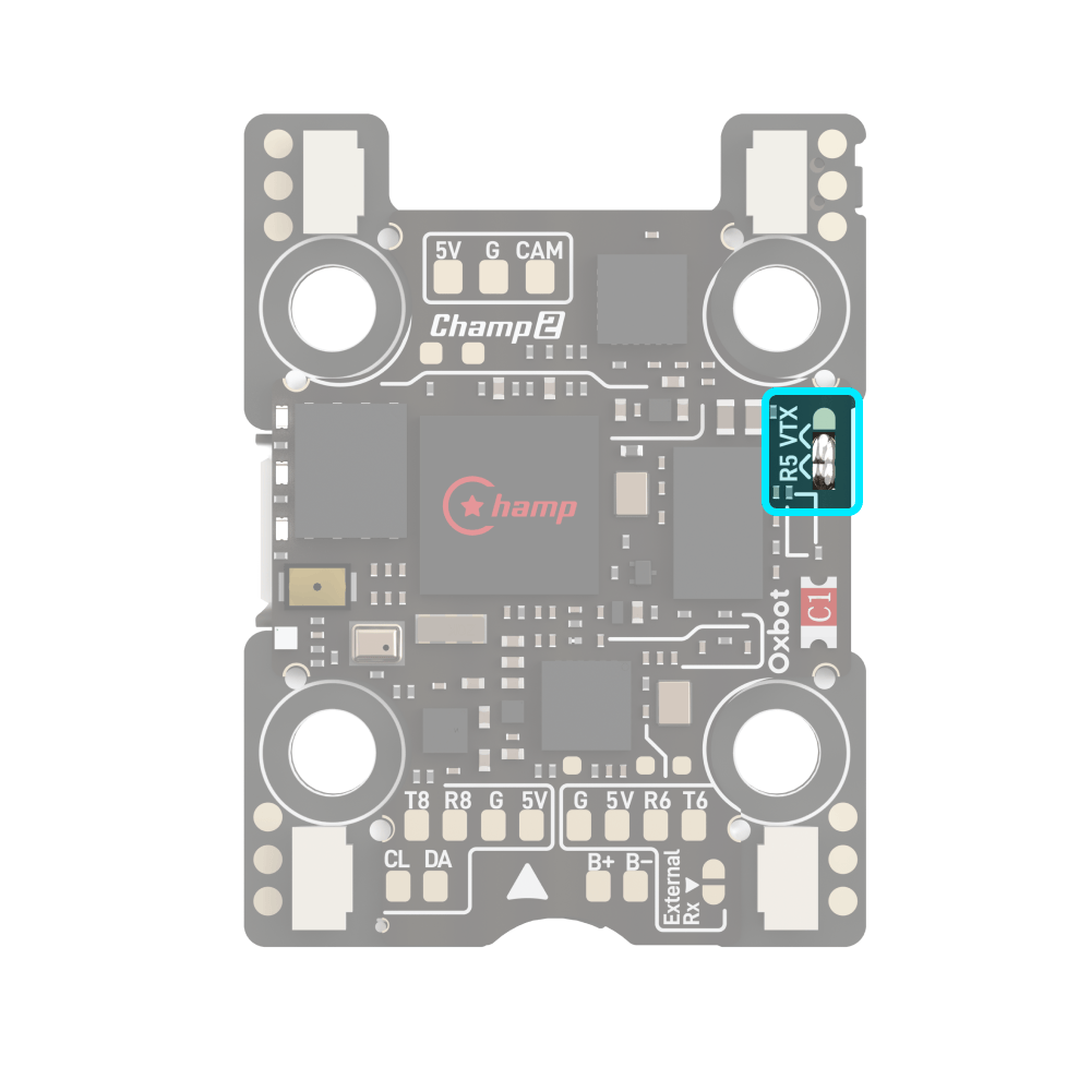 |
| 启用外置接收机跳线External receiver enable jumper | 作用:用于控制内置接收机供电。 使用外置接收机时:短接该跳线,关闭内置接收机供电,再将外置接收机连接至 UART6。Function: Controls power to the built-in receiver. When using an external receiver: bridge this jumper to disable power to the built-in receiver, then connect the external receiver to UART6. | 不短接,启用内置接收机Open, built-in receiver enabled | 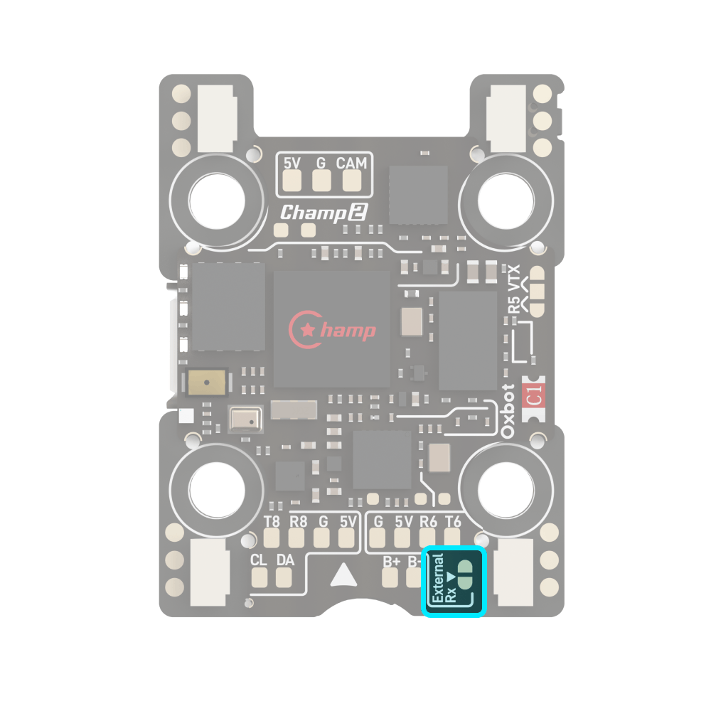 |
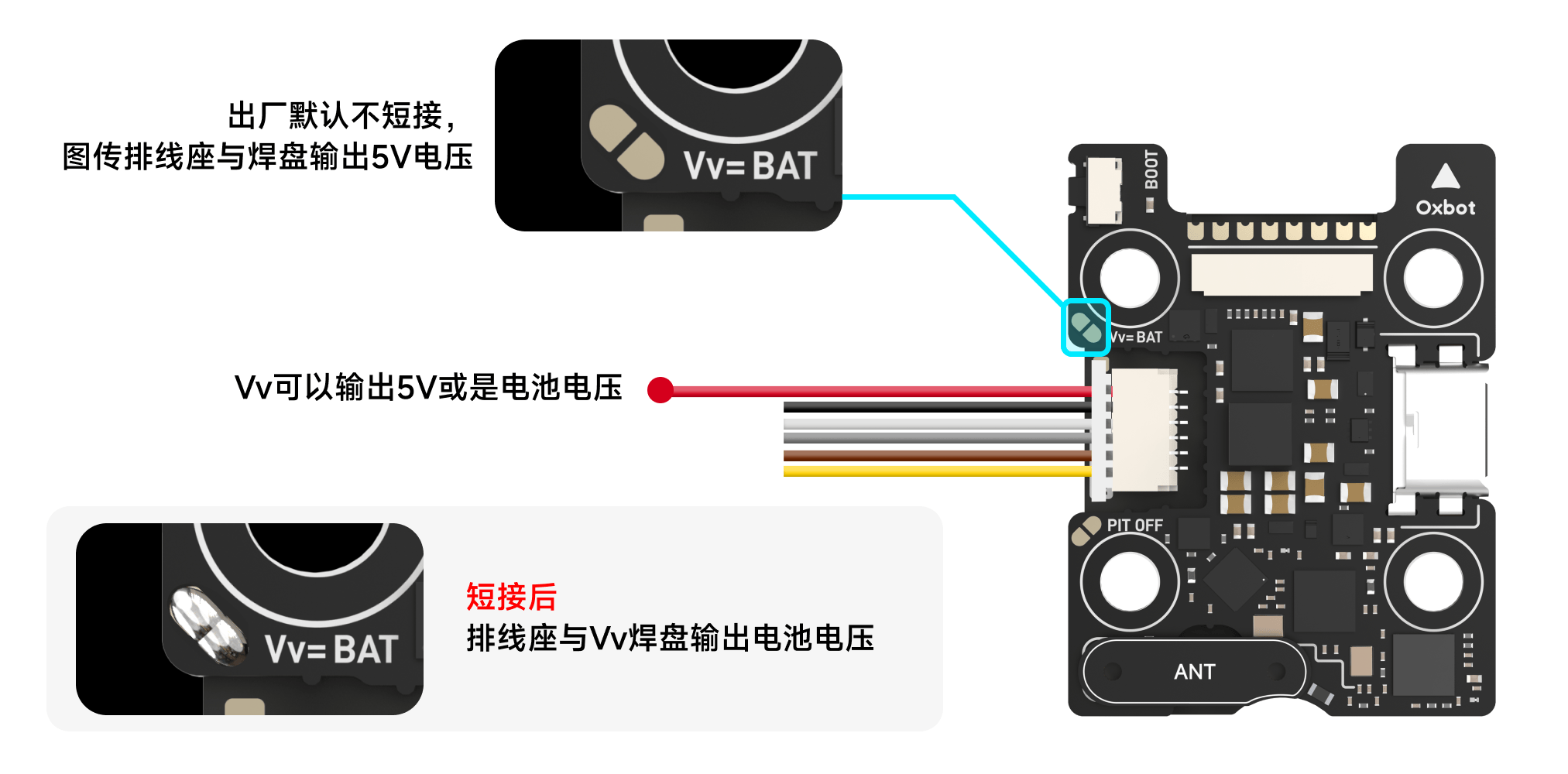
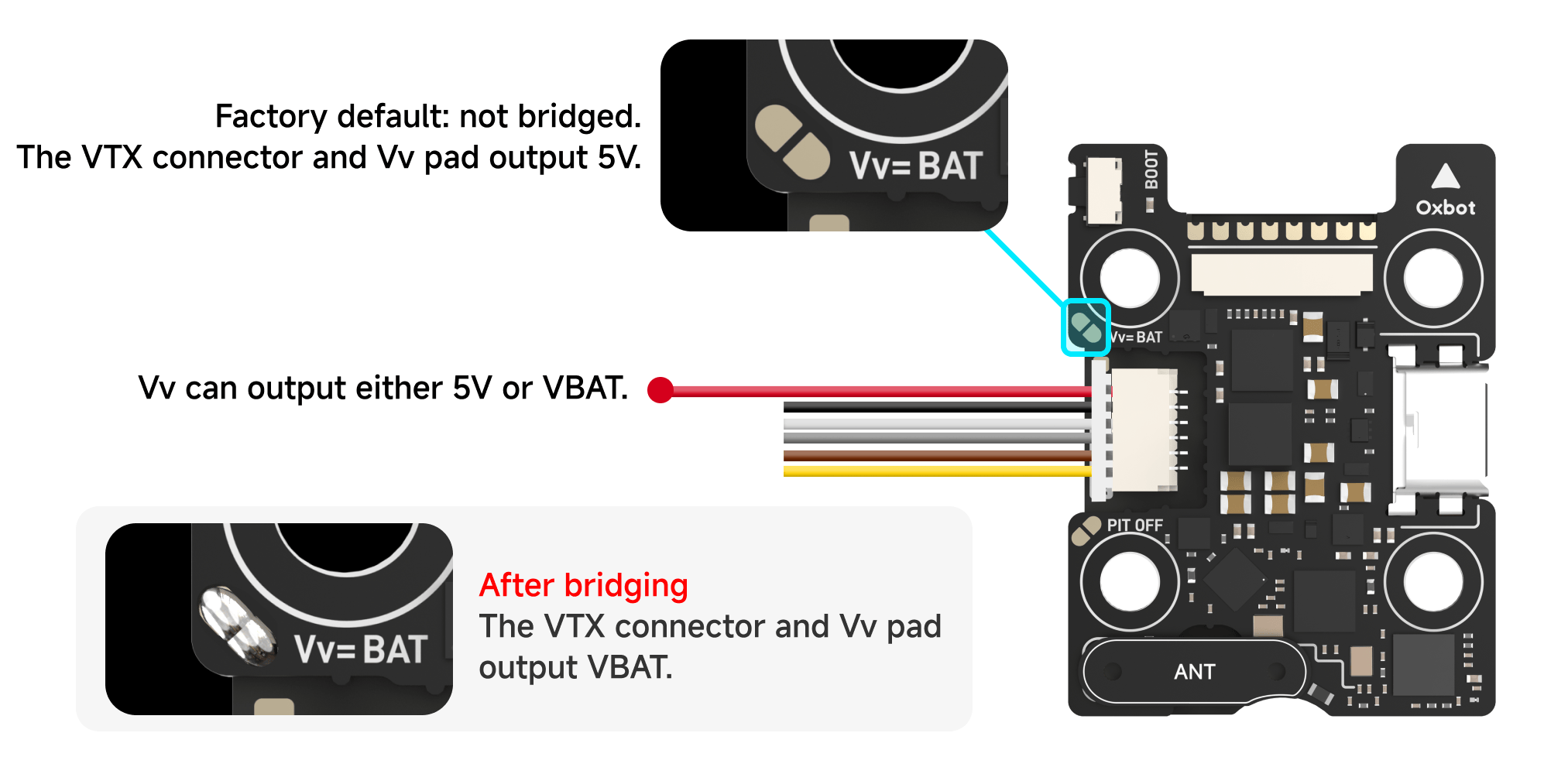
| 图传电压切换跳线VTX voltage jumper | 作用:用于切换图传接口输出电压。 未短接:图传接口输出 5V。短接后:图传接口输出 BAT(电池电压)。 警告:切换到 BAT 前,请确认图传支持电池电压输入。只支持 5V 输入的图传禁止切换到 BAT。Function: Selects the output voltage for the VTX port. Open: the VTX port outputs 5V. Bridged: the VTX port outputs BAT (battery voltage). Warning: Before switching to BAT, confirm your VTX supports battery-voltage input. Do not switch to BAT for VTX units that only support 5V input. | 不短接,使用 5V 供电Open, 5V output | 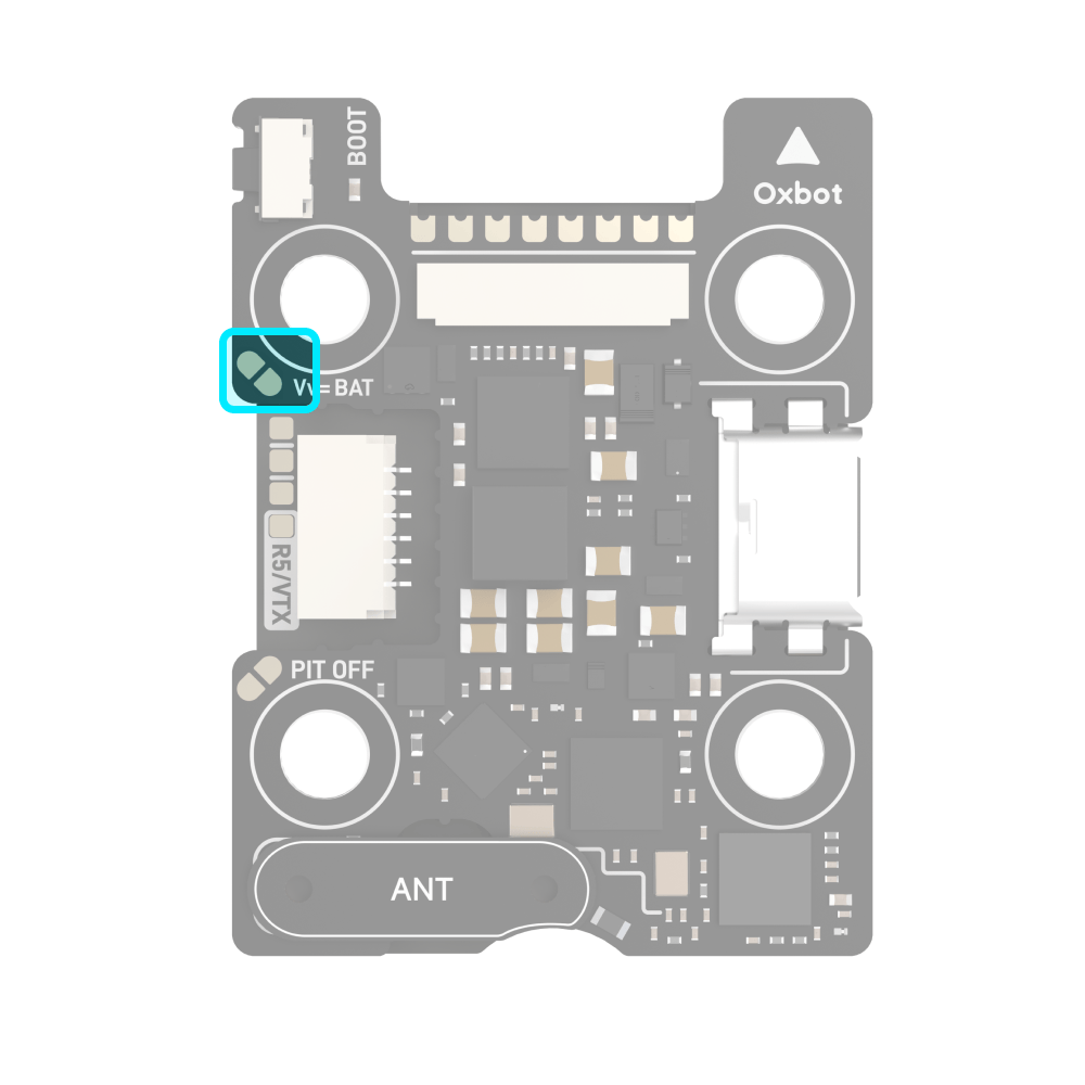 |
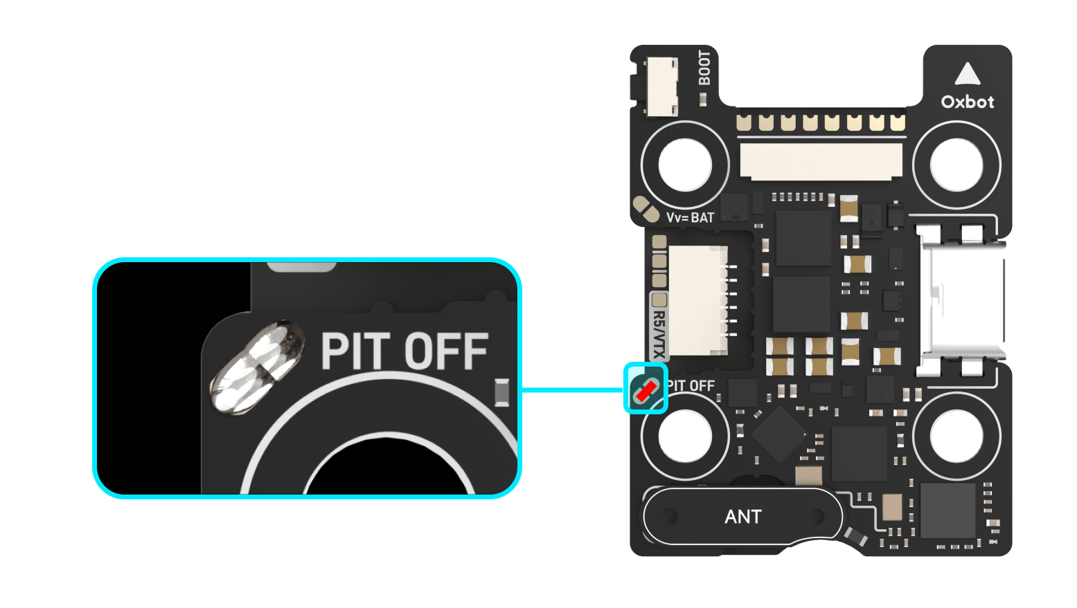
| 图传供电关闭禁用跳线VTX power-off disable jumper | 作用:用于控制图传供电是否允许通过模式开关关闭。 未短接:可通过 "VTX BEC OFF" 模式关闭图传供电;未设置该模式时,图传供电常开。 短接后:图传供电无法通过模式开关关闭。Function: Controls whether VTX power can be disabled by a mode switch. Open: VTX power can be turned off using the "VTX BEC OFF" mode; if that mode is not configured, VTX power stays on. Bridged: VTX power cannot be turned off using a mode switch. | 不短接,允许模式关闭图传供电Open, mode-controlled VTX power is allowed | 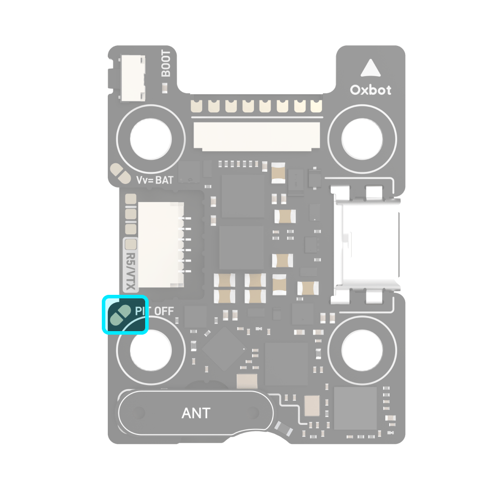 |
三、外设连接概览2.3 Peripheral Overview
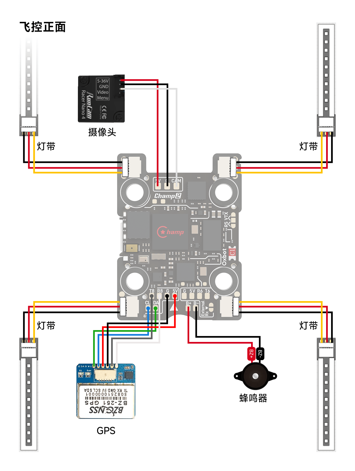
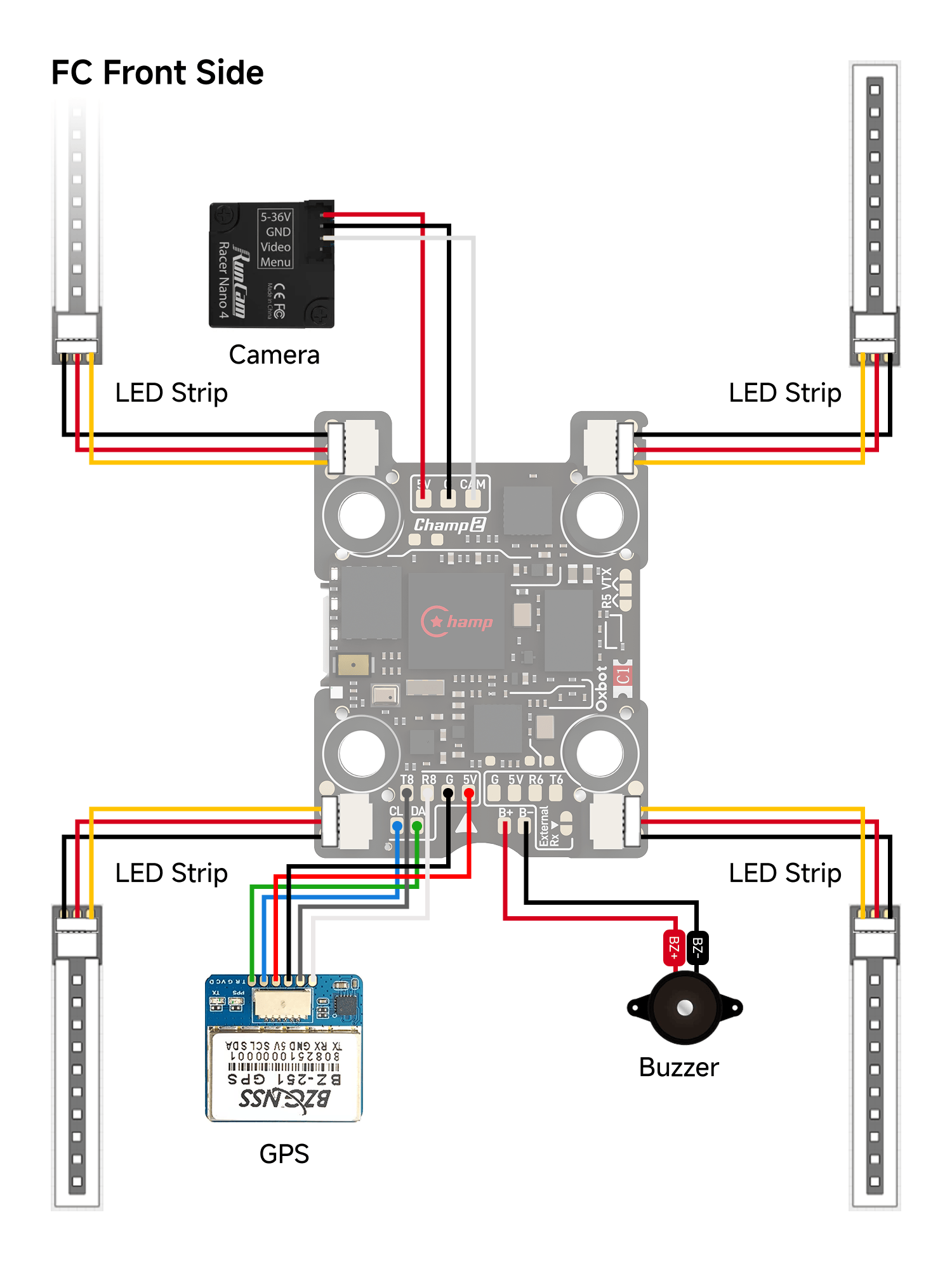
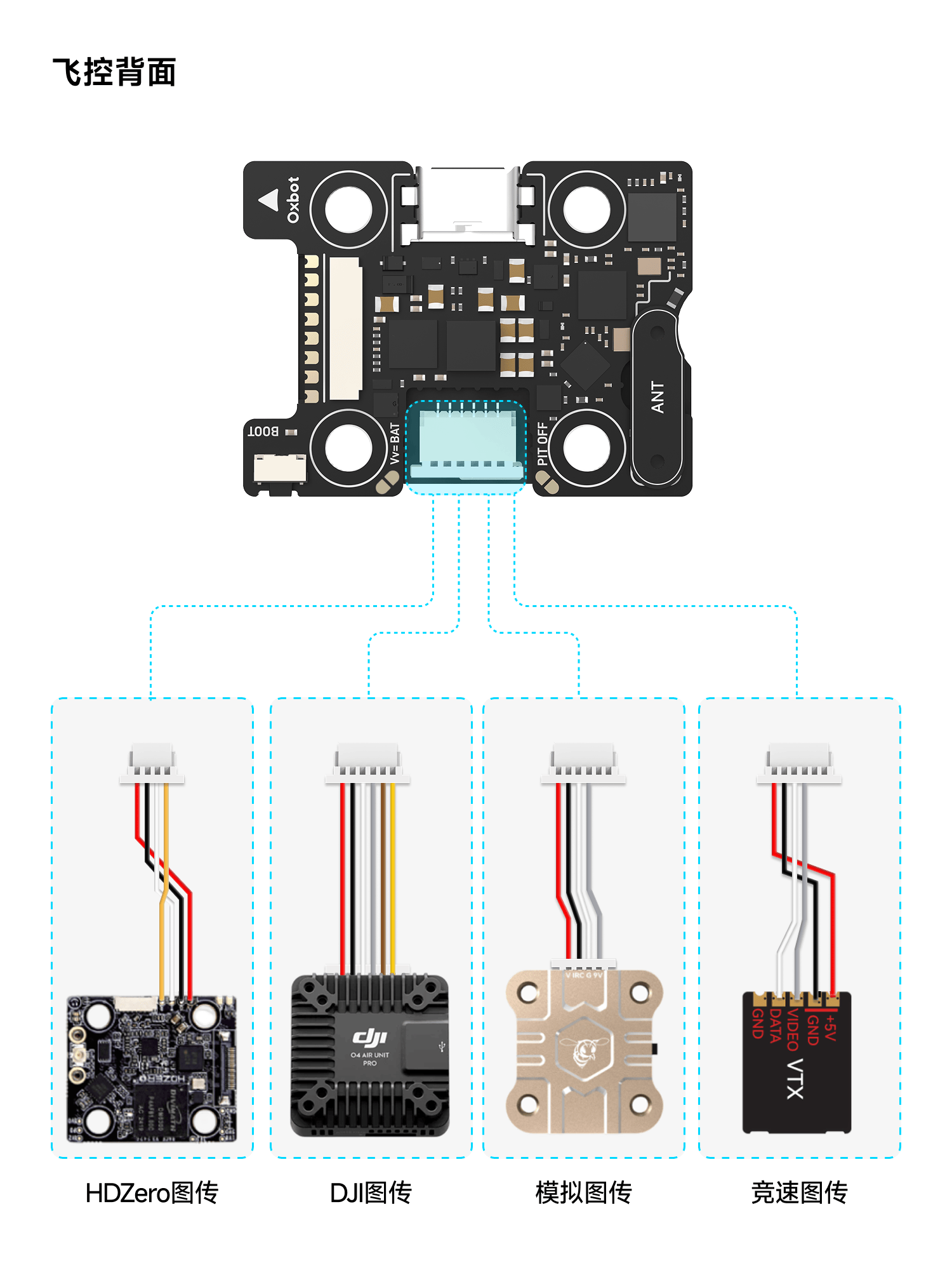
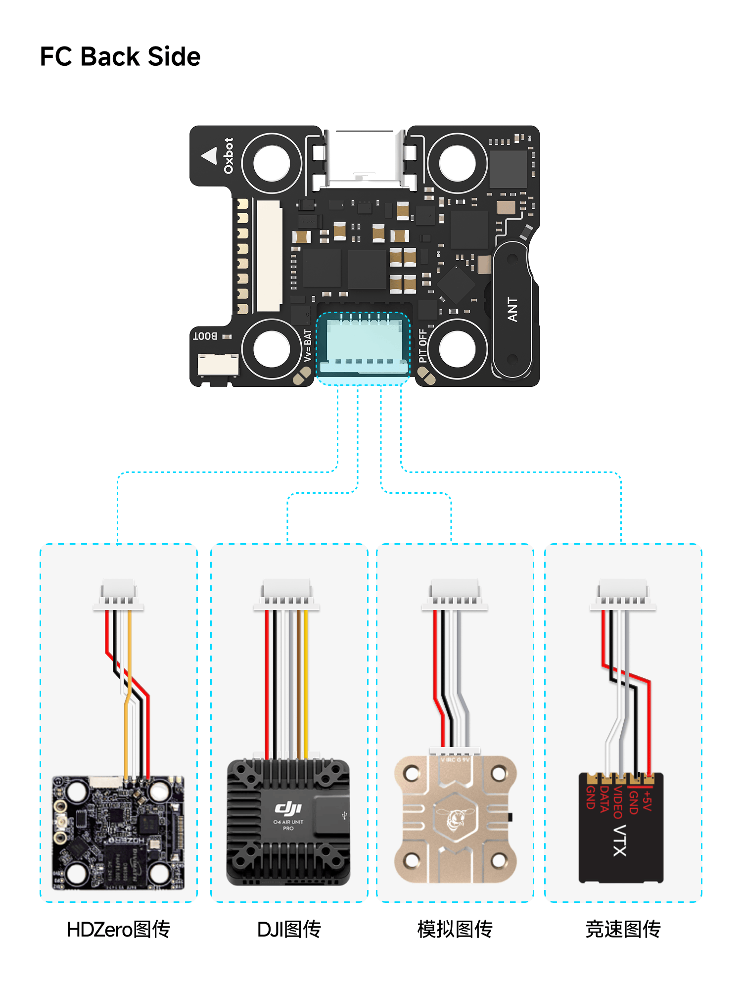
四、外设连接详情2.4 Peripheral Details
1. LED 灯带2.4.1 LED Strip
LED 灯带供电带有独立短路保护。若炸机后灯带损坏并短路,飞控会自动切断灯带供电,避免影响飞行。The LED strip power output includes independent short-circuit protection. If the strip is damaged and shorts after a crash, the FC will automatically cut power to the strip so the rest of the system is not affected.
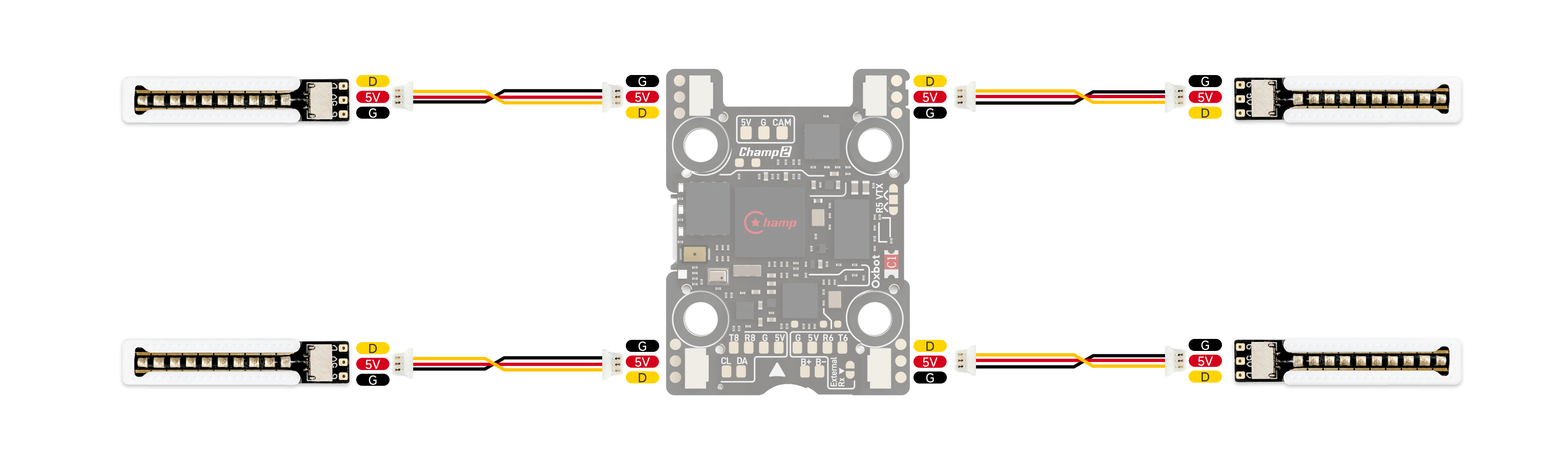
连接方式一:排线连接Method 1: cable connection
飞控带有四个 SUR0.8 的排线座,可以通过飞控配的排线直接连接 OXBOT 竞速灯带。The flight controller has four SUR0.8 connectors, allowing you to connect an OXBOT racing LED strip directly with the included cable.
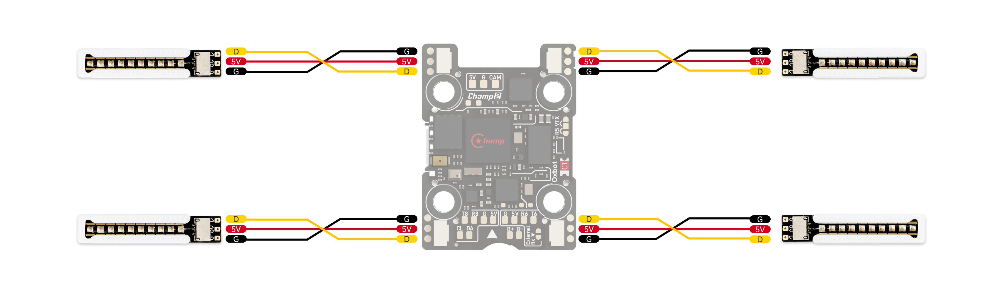
连接方式二:焊接连接Method 2: soldered connection
飞控预留有LED灯带焊盘,也支持通过焊接将飞控连接到其他的WS2812协议的灯带Dedicated LED pads are also provided, so the FC can be soldered to other WS2812-compatible LED strips.
流星灯效设置2.4.2 Meteor Effects
方式一:通过 App 设置Method 1: configure in the app
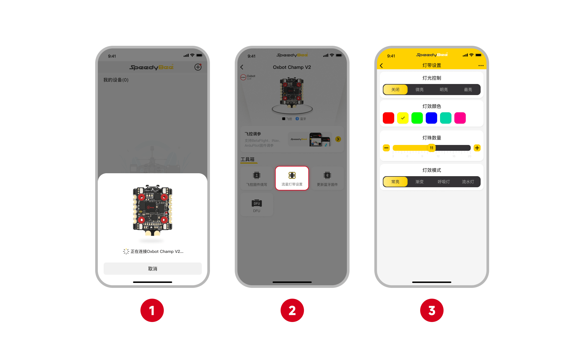
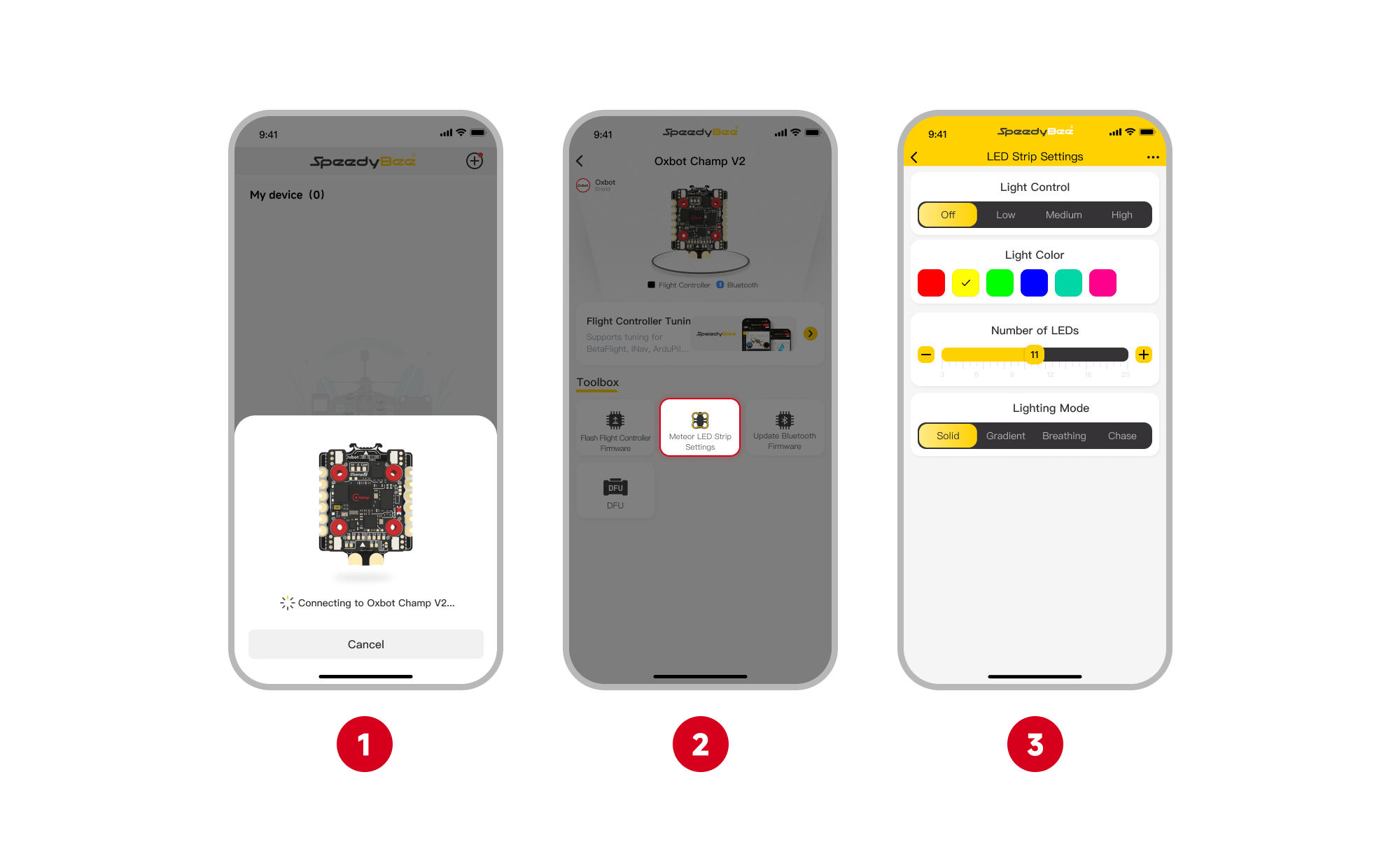
步骤 1:连接飞控后,打开 SpeedyBee / 快蜂 App,进入【工具箱】,点击【流星灯带设置】。Step 1: after connecting to the FC, open the SpeedyBee app, go to Toolbox, and tap Meteor LED Settings.
步骤 2:等待 App 与飞控建立连接。连接成功后,系统将自动进入灯带设置页面。Step 2: wait for the app to establish a connection with the FC. Once connected, it will open the LED settings page automatically.
步骤 3:根据实际需要设置灯光控制方式、灯效颜色、灯珠数量和灯效模式。设置完成后,点击保存即可生效。Step 3: configure the control mode, effect color, LED count, and effect pattern as needed. Tap save to apply the changes.
方式二:通过 BOOT 按键设置Method 2: configure using the BOOT button
也可以通过飞控上的 BOOT 按键 快速调整流星灯效:You can also adjust meteor lighting effects quickly using the BOOT button on the FC:
| 操作方式Action | 功能说明Function |
|---|---|
| 短按 BOOT 按键 2 次Short-press BOOT twice | 切换灯效颜色,颜色将在红、黄、绿、蓝、青、品红之间循环Cycles the effect color through red, yellow, green, blue, cyan, and magenta. |
| 长按 BOOT 按键 1 秒Hold BOOT for 1 second | 调整灯效亮度Adjusts LED brightness. |
2. 接收机2.4.3 Receiver
内置 ELRS 接收机Built-in ELRS Receiver
飞控内置 ELRS 2.4GHz 接收机,可与 ELRS 2.4GHz 遥控器或高频头对频使用。对频前请确认双方频段、对频短语和 Model Match 设置一致。The FC includes a built-in ELRS 2.4GHz receiver and can bind directly with ELRS 2.4GHz radios or TX modules. Before binding, make sure the band, binding phrase, and Model Match settings are the same on both sides.
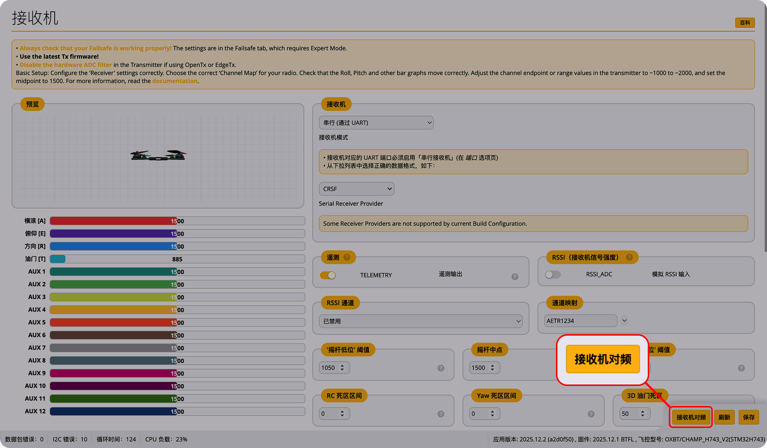
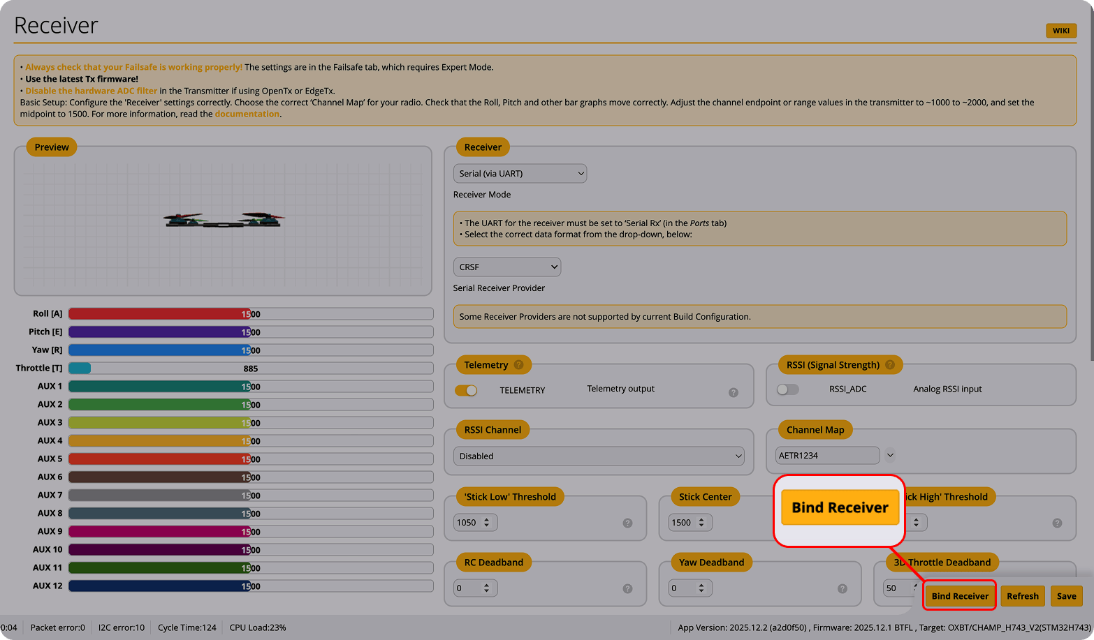
内置接收机对频:Binding the built-in receiver: 连接地面站后,进入接收机页面,点击【接收机对频】选项即可进入对频状态。接收机进入对频状态后,ELRS 状态灯会连续闪烁两次。再将遥控器或高频头进入对频状态,连接成功后 ELRS 状态灯变为常亮。After connecting to the configurator, open the receiver page and tap Bind Receiver to enter bind mode. In bind mode, the ELRS status LED will blink twice repeatedly. Then put the radio or TX module into bind mode. Once binding succeeds, the ELRS status LED will stay solid.
提示:Tip:
- 为保证设备稳定运行,请确认高频头固件版本不低于 3.6.0,建议使用 3.6.4。较低版本固件可能存在兼容性问题,导致接收机异常。For stable operation, make sure your TX module firmware is not older than 3.6.0; 3.6.4 is recommended. Older firmware may have compatibility issues and can cause receiver problems.
外置 ELRS 接收机External ELRS Receiver
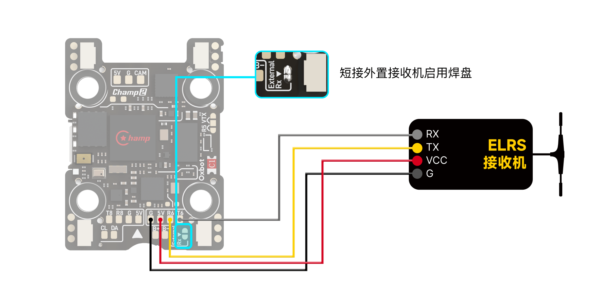
接线指引:Wiring: 使用外置 ELRS 接收机时,请先通过外置接收机跳线关闭内置接收机,再将ELRS 接收机连接到飞控 UART6。When using an external ELRS receiver, first disable the built-in receiver by bridging the external receiver jumper, then connect the ELRS receiver to UART6 on the FC.
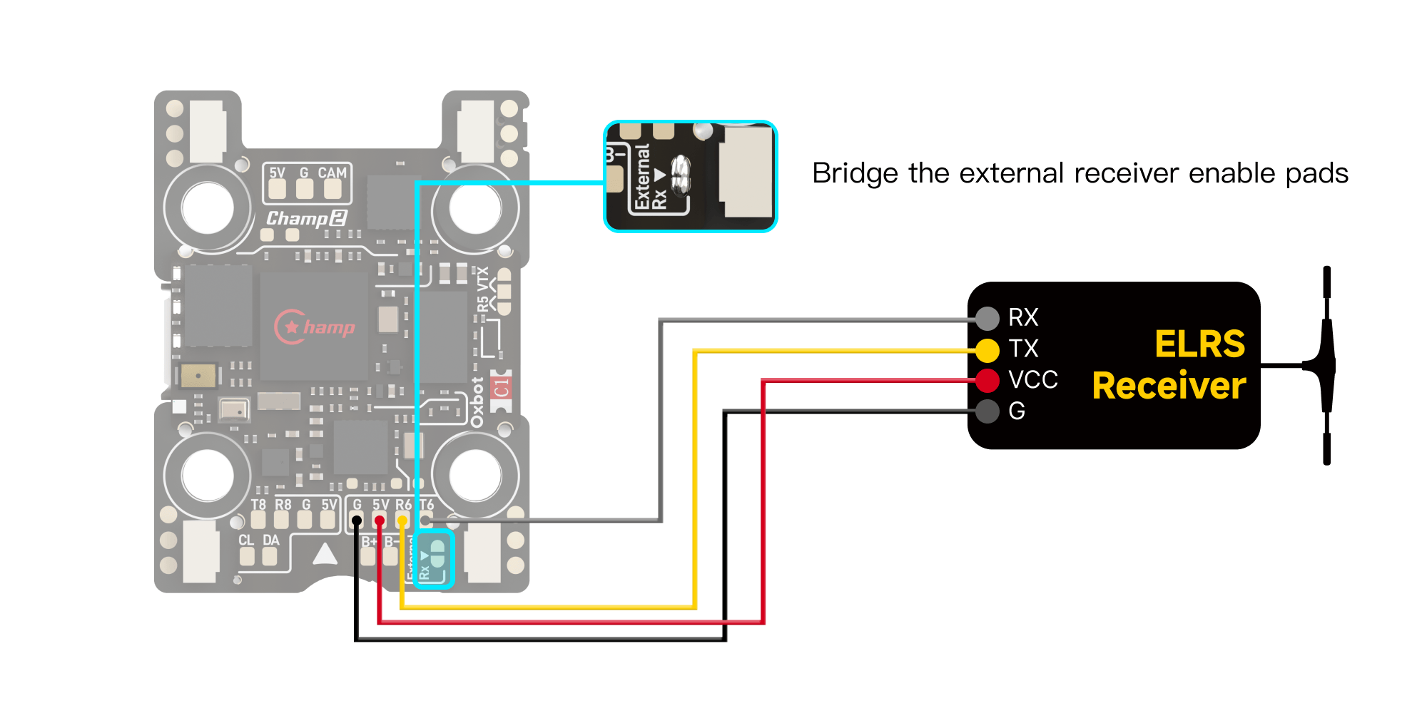
接收机设置Receiver setup
无需额外设置No additional setup is required.
TBS Crossfire 接收机TBS Crossfire Receiver
接线指引:Wiring: 使用 TBS 接收机时,请先通过外置接收机跳线关闭内置接收机,再将TBS 接收机连接到飞控 UART6。When using a TBS receiver, first disable the built-in receiver with the external receiver jumper, then connect the TBS receiver to UART6 on the FC.
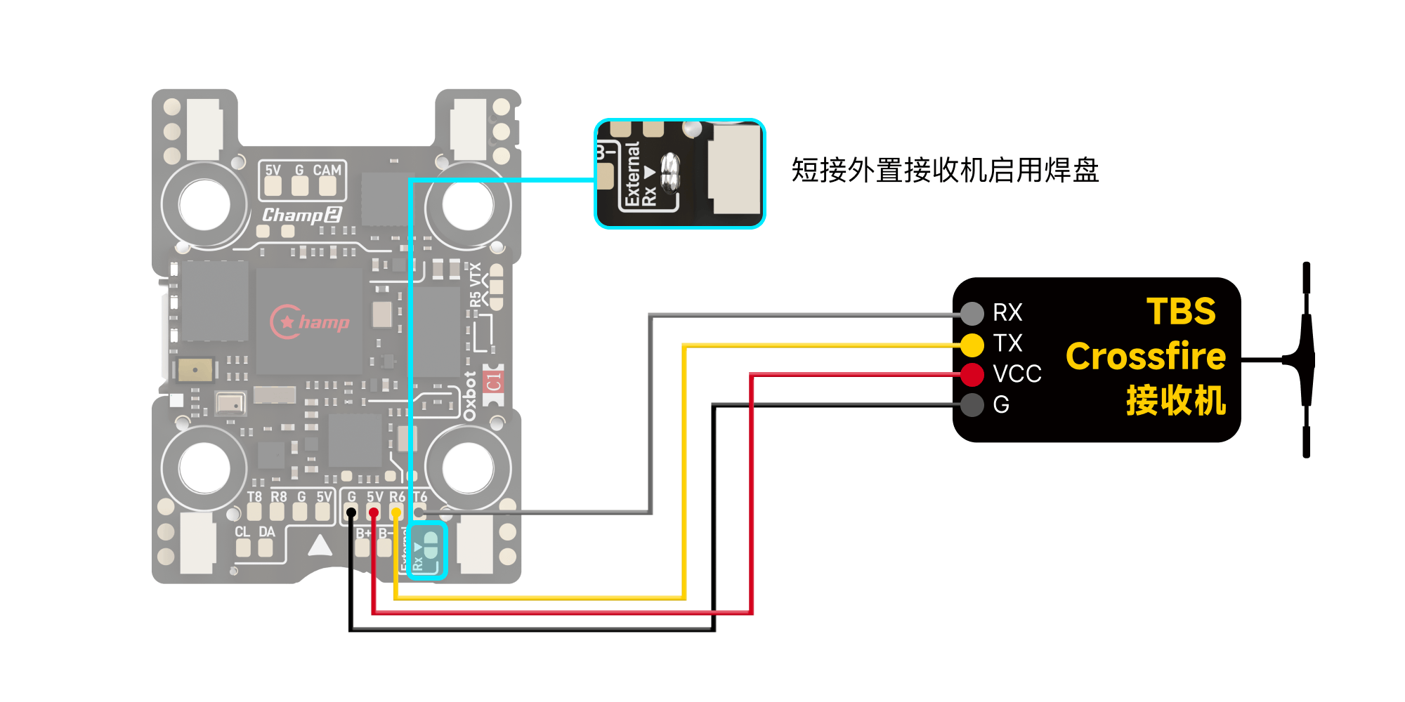
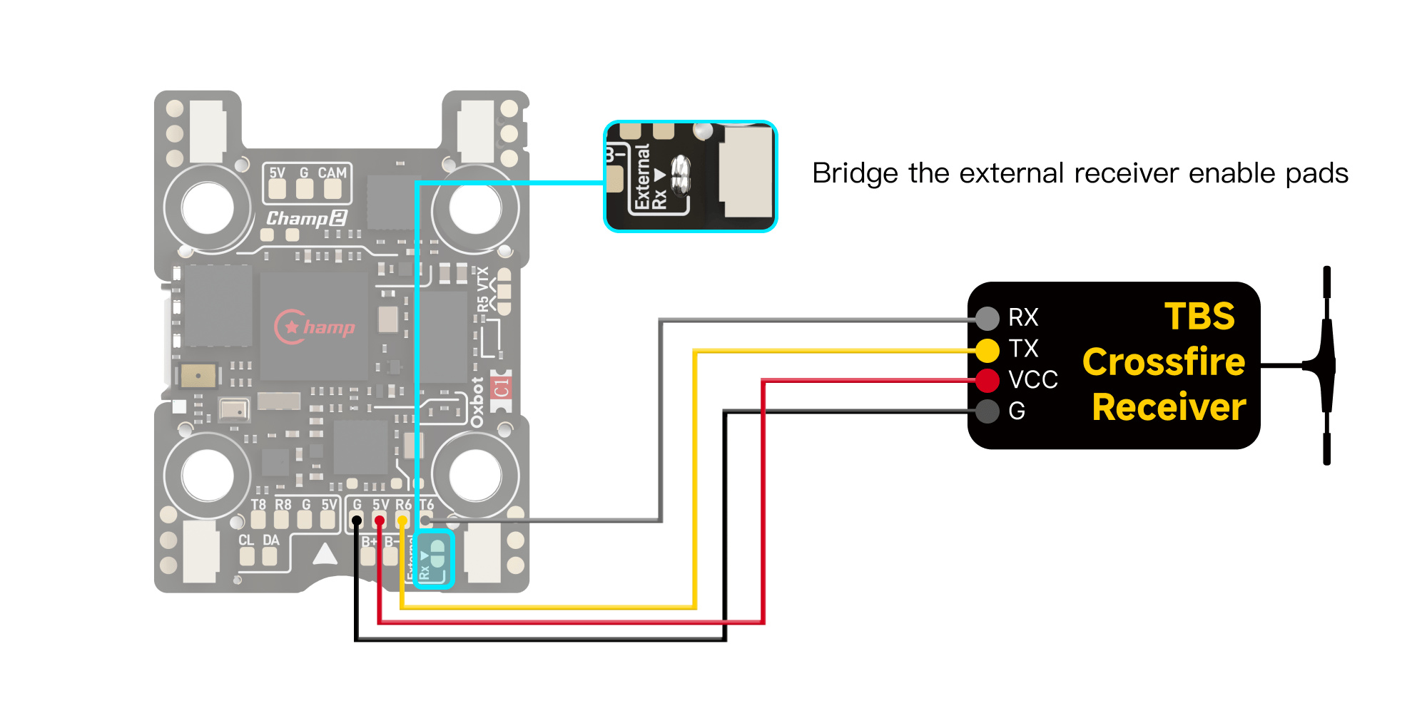
接收机设置Receiver setup
无需额外设置No additional setup is required.
SBUS 接收机SBUS Receiver
接线指引:Wiring: 外置SBUS接收机的信号线需要连接到飞控的天空端排线座中The signal wire of an external SBUS receiver should be connected to the air-unit side connector on the FC.
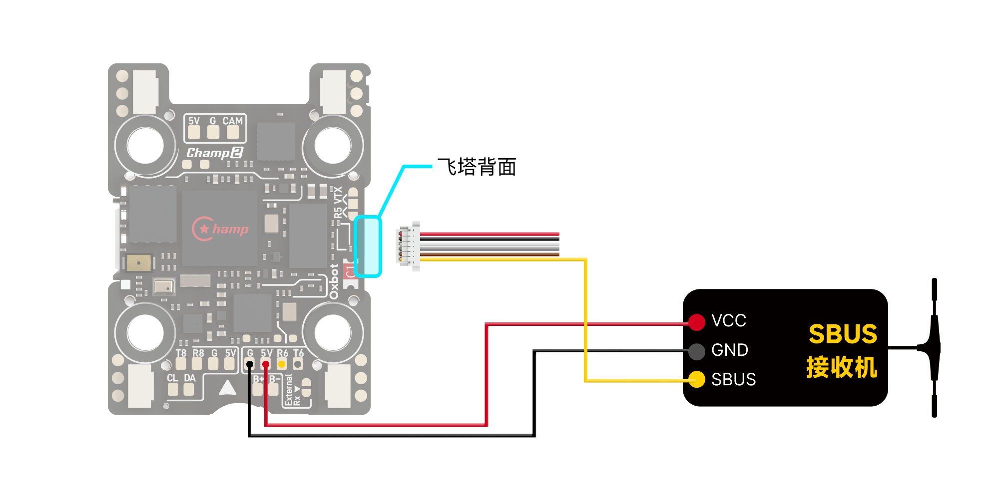
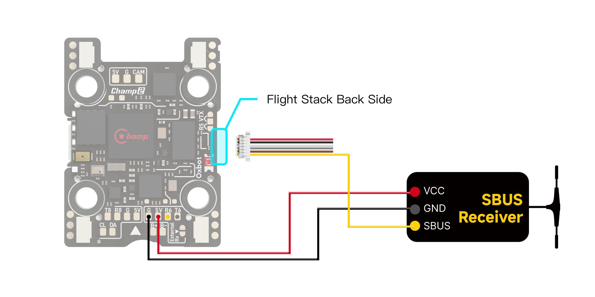
接收机设置Receiver setup
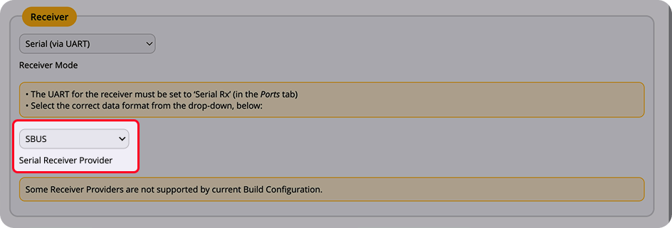
- 关闭UART6的接收机端口并开启UART7的接收机Disable the receiver port on UART6 and enable the receiver port on UART7.
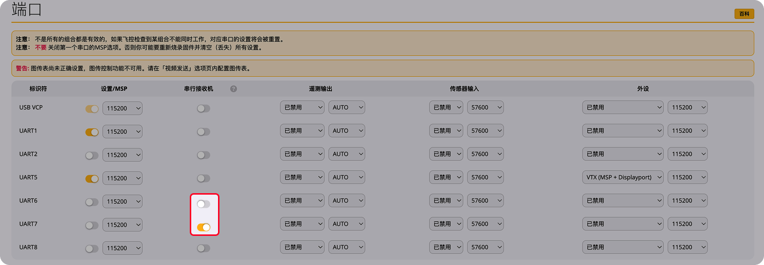
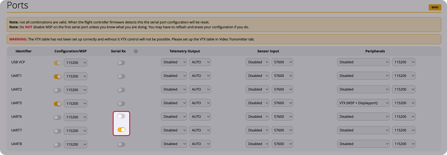
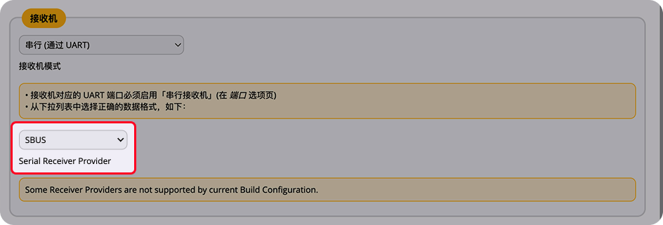
- 将接收机协议切换为SBUSSet the receiver protocol to SBUS.
天空端内置 SBUS 接收机Onboard SBUS Receiver
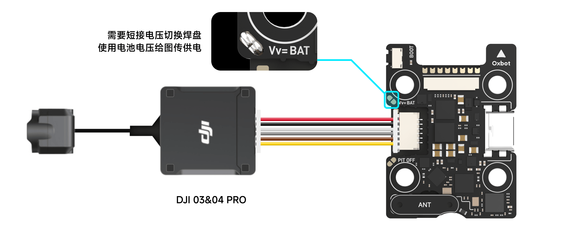
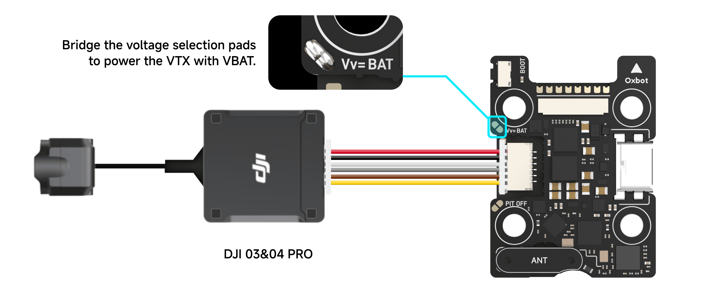
接线指引:Wiring: 使用天空端附带的6PIN排线将天空端连接到飞控Use the 6-pin cable supplied with the air unit to connect it to the flight controller.
接收机设置Receiver setup
- (1)关闭UART6的接收机端口并开启UART7的接收机(1) Disable the receiver port on UART6 and enable the receiver port on UART7.
- (2)将接收机协议切换为SBUS(2) Set the receiver protocol to SBUS.
在眼镜中确认接收机速率为 Standard 或 Fast,如为 Fast 需在 CLI 输入:In the goggles, confirm the receiver rate is set to Standard or Fast. If Fast is selected, enter the following CLI command: set sbus_baud_fast = ON
3. 图传2.4.4 Video Transmitter
图传供电跳线:VTX power jumper: 飞控图传接口默认输出 5V。若使用支持宽电压输入的图传,可通过背面的图传供电选择焊盘,将图传供电切换为电池电压。The VTX port outputs 5V by default. If your VTX supports wide-voltage input, you can switch the VTX power selector pad on the back to battery voltage.
高清模拟切换跳线:HD / analog signal jumper: 飞控的图传排线座与焊盘的第四 PIN 支持在 R5 与 VTX 之间切换。Pin 4 on the VTX connector and matching pad can be switched between R5 and VTX.
PIT / VTX BEC OFF 图传供电关闭功能PIT / VTX BEC OFF VTX Power Cut-Off Feature
CHAMP 2 支持通过 Betaflight 或 SpeedyBee APP 开启 VTX BEC OFF 模式,用于临时关闭图传端口供电。CHAMP 2 supports enabling VTX BEC OFF mode via Betaflight or SpeedyBee APP to temporarily turn off power to the VTX port.
当 VTX BEC OFF 模式未设置或未激活时,图传端口正常供电;When the VTX BEC OFF mode is not set or not activated, the VTX port is powered normally;
当 VTX BEC OFF 模式激活时,飞控会切断图传端口的电压输出。when the VTX BEC OFF mode is activated, the FC cuts off the voltage output of the VTX port.


如果不希望遥控器模式关闭图传供电,可短接飞控背面的 PIT OFF 跳线焊盘。短接后,图传端口将保持供电输出,不再受 VTX BEC OFF 模式控制。If you do not want to use the radio transmitter mode to turn off VTX power, you can bridge the PIT OFF jumper pads on the back of the FC. Once bridged, the VTX port will maintain its power output and is no longer controlled by the VTX BEC OFF mode.
图传兼容表VTX compatibility table
| 图传类型 / 型号VTX Type / Model | 图传供电跳线Power Jumper | 信号跳线Signal Jumper | Betaflight 设置Betaflight Settings |
|---|---|---|---|
| HDZero Race V3 | 保持默认:5VLeave at default: 5V | 保持默认:R5Leave at default: R5 | 无需修改No change required |
| DJI O4 Lite | 保持默认:5VLeave at default: 5V | 保持默认:R5Leave at default: R5 | 无需修改No change required |
| DJI O4 Pro | 切换为 BAT/VBAT,输出电池电压Switch to BAT/VBAT for battery-voltage output | 保持默认:R5Leave at default: R5 | 无需修改No change required |
| 5V 供电模拟图传(如 Rush Tank Race II)5V analog VTX (for example Rush Tank Race II) | 保持默认:5VLeave at default: 5V | 断开 R5,短接 VTXOpen R5 and bridge VTX | 需按模拟图传设置修改 Betaflight 端口和 OSD 输出Change Betaflight ports and OSD output for analog VTX use |
| 宽电压输入模拟图传Wide-voltage analog VTX | 切换为 BAT,输出电池电压Switch to BAT for battery-voltage output | 断开 R5,短接 VTXOpen R5 and bridge VTX | 需按模拟图传设置修改 Betaflight 端口和 OSD 输出Change Betaflight ports and OSD output for analog VTX use |
HDZero Race V3
接线指引:Wiring: 推荐使用随包附带的 15mm 6P SH1.0 排线连接 HDZero 图传,可减少线材长度,使装机更简洁。连接前请确认排线方向。Use the included 15mm 6P SH1.0 cable to connect the HDZero VTX. This keeps wiring short and makes the build cleaner. Confirm cable orientation before plugging it in.
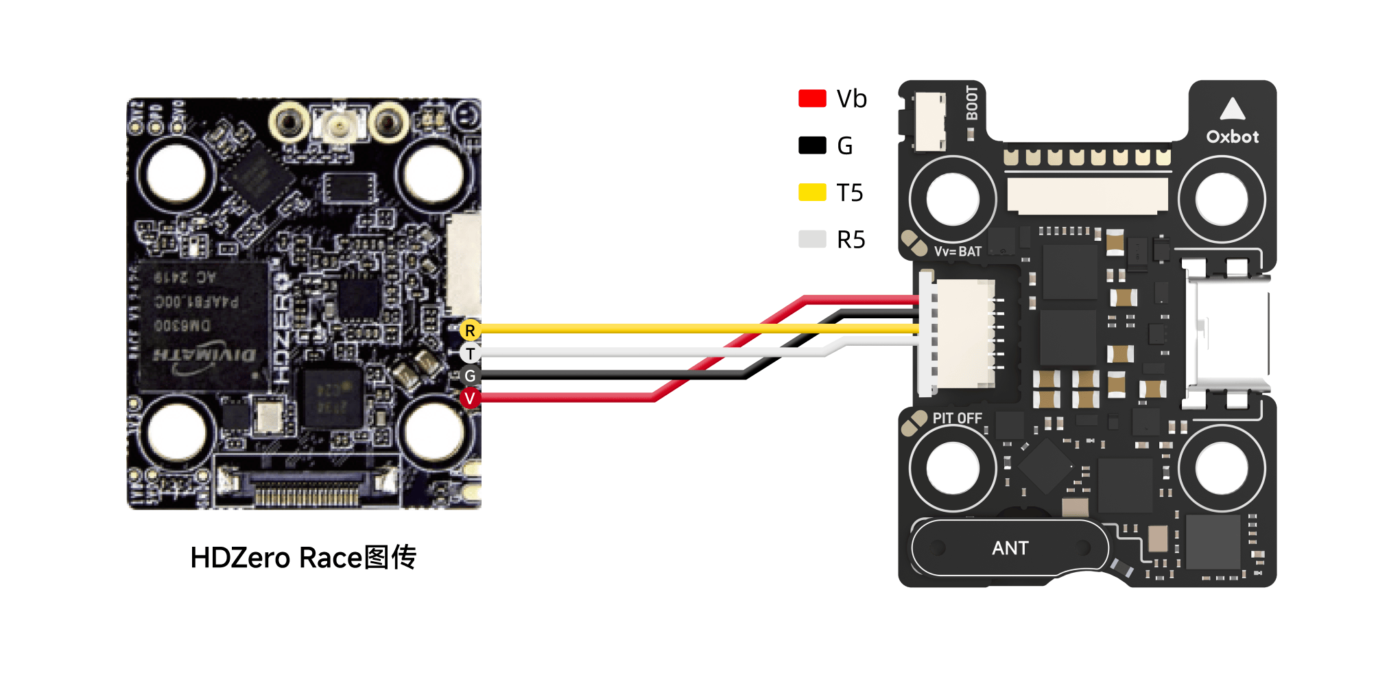
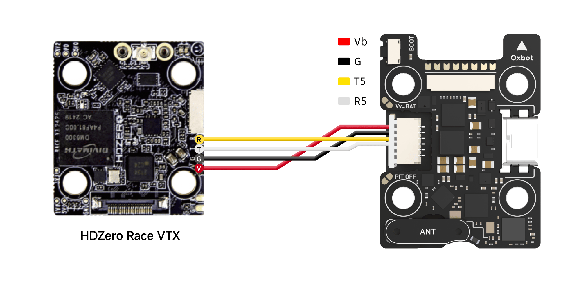
图传设置:VTX setup: 出厂默认按高清图传配置,UART5 的 MSP 已开启,OSD 输出为 MSP DisplayPort。使用高清图传时,通常无需修改 Betaflight 设置。The FC ships configured for digital HD VTX use. MSP on UART5 is enabled by default, and OSD output is set to MSP DisplayPort. In most cases, no Betaflight changes are required for HD systems.
DJI O4 Lite
接线指引:Wiring: 可使用 DJI 原装排线直接连接。插入前请确认接口方向和线序一致。The DJI stock cable can be used directly. Check connector orientation and wire order before inserting it.
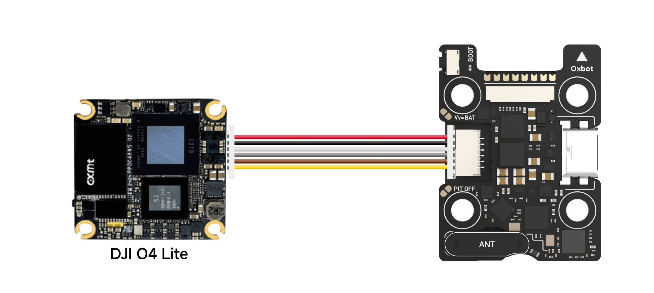
图传设置:VTX setup: 出厂默认按高清图传配置,UART5 的 MSP 已开启,OSD 输出为 MSP DisplayPort。使用高清图传时,通常无需修改 Betaflight 设置。The FC ships configured for digital HD VTX use. MSP on UART5 is enabled by default, and OSD output is set to MSP DisplayPort. In most cases, no Betaflight changes are required for HD systems.
DJI O3 / DJI O4 Pro
接线指引:Wiring: 可使用 DJI 原装排线直接连接。插入前请确认接口方向和线序一致。The DJI stock cable can be used directly. Check connector orientation and wire order before inserting it.
图传设置:VTX setup: 出厂默认按高清图传配置,UART5 的 MSP 已开启,OSD 输出为 MSP DisplayPort。使用高清图传时,通常无需修改 Betaflight 设置。The FC ships configured for digital HD VTX use. MSP on UART5 is enabled by default, and OSD output is set to MSP DisplayPort. In most cases, no Betaflight changes are required for HD systems.
5V 模拟图传5V Analog VTX
接线指引:Wiring: 可使用随包附带的 4P 图传排线连接模拟图传。飞控端插入图传排线座,图传端按 +5V、GND、DATA、VTX 顺序焊接或插接。不同图传线序可能不同,焊接前必须核对图传丝印和线序。飞控同时保留图传焊盘,也可通过焊接方式连接。Use the included 4-pin VTX cable to connect an analog VTX. Plug the FC side into the VTX connector, then solder or plug the VTX side in the order of +5V, GND, DATA, and VTX. Wire order varies between VTX models, so always verify the silkscreen and pinout before soldering. The FC also keeps dedicated VTX pads for direct soldering if needed.
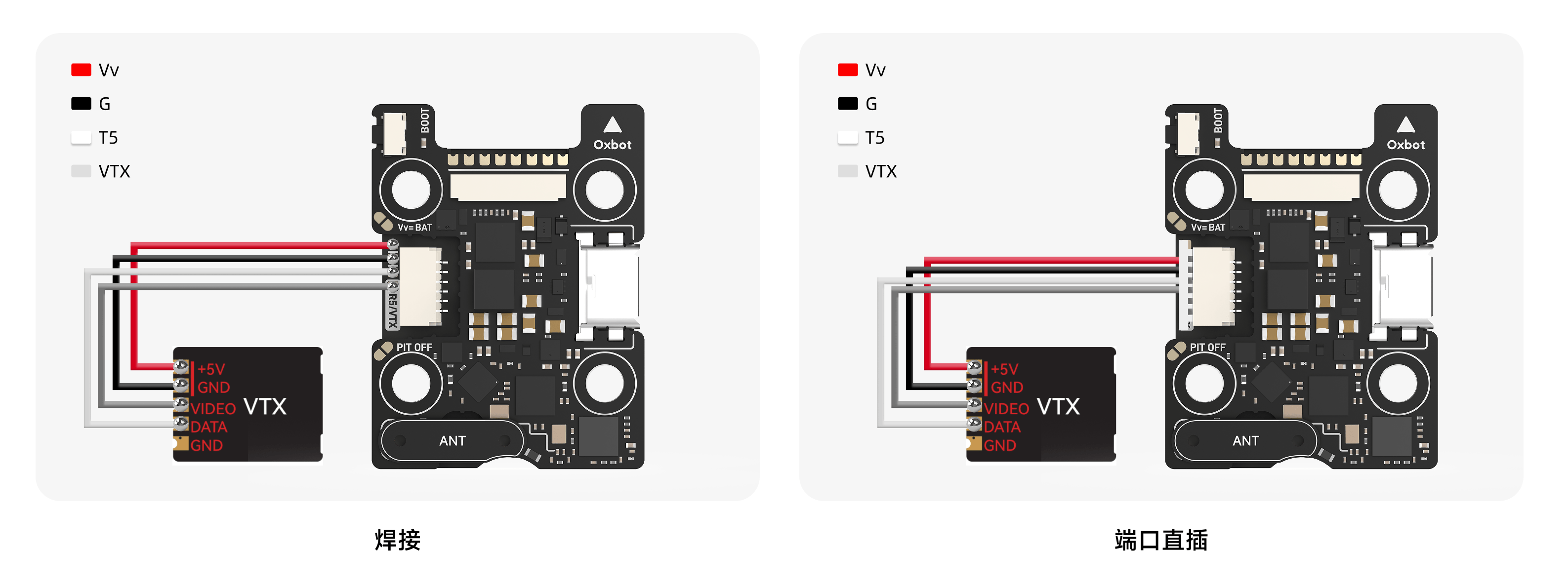
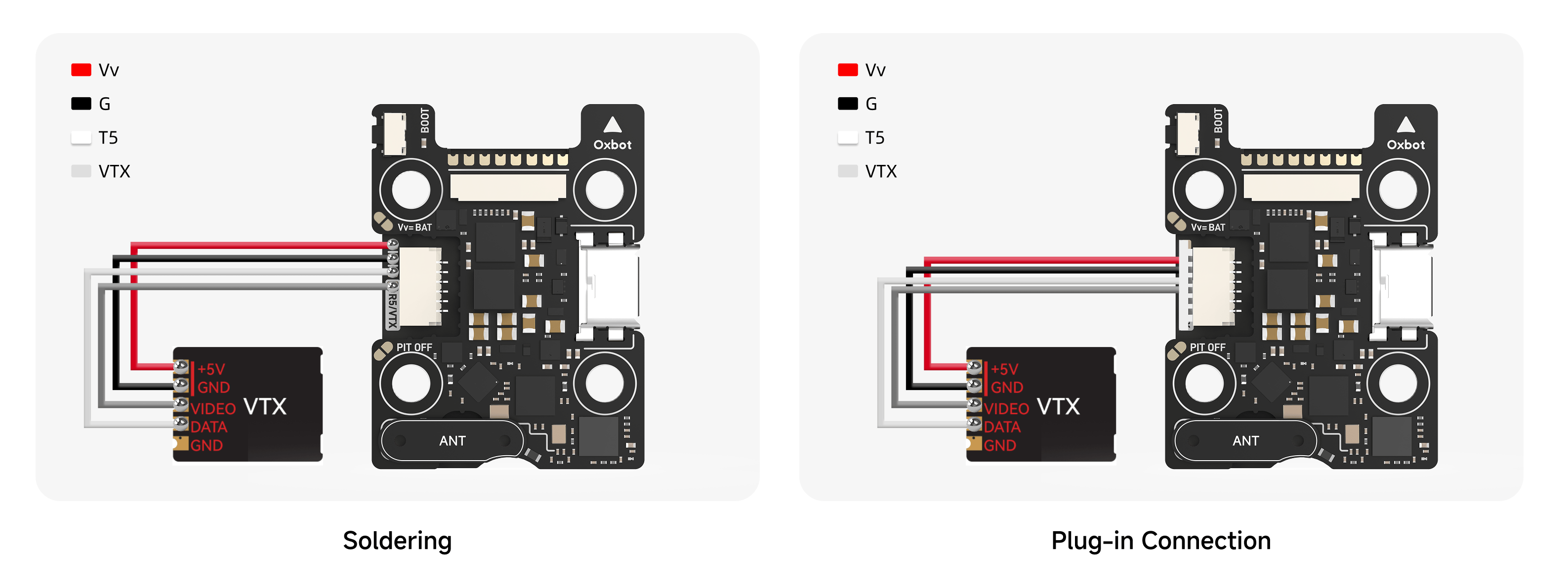
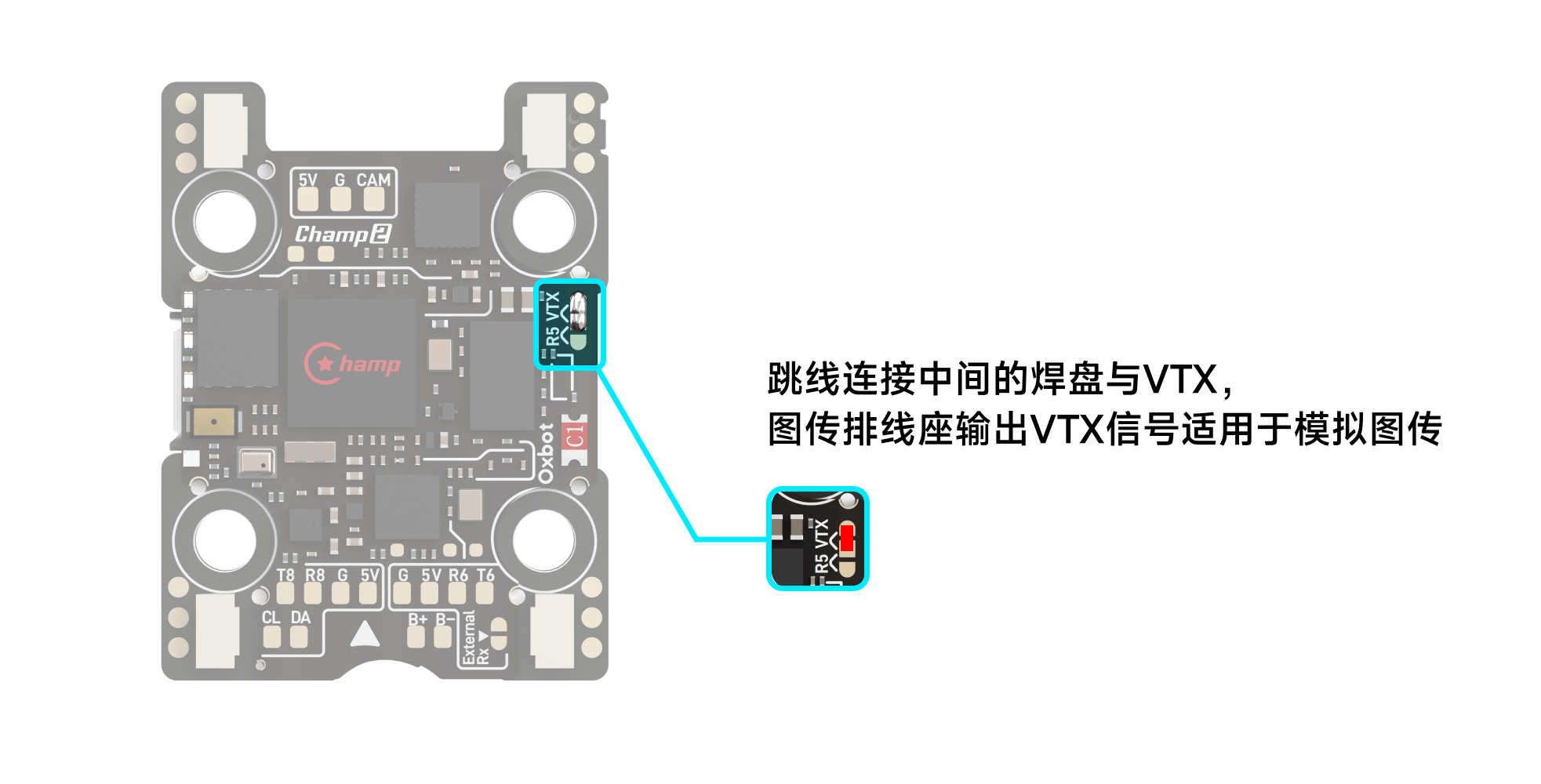
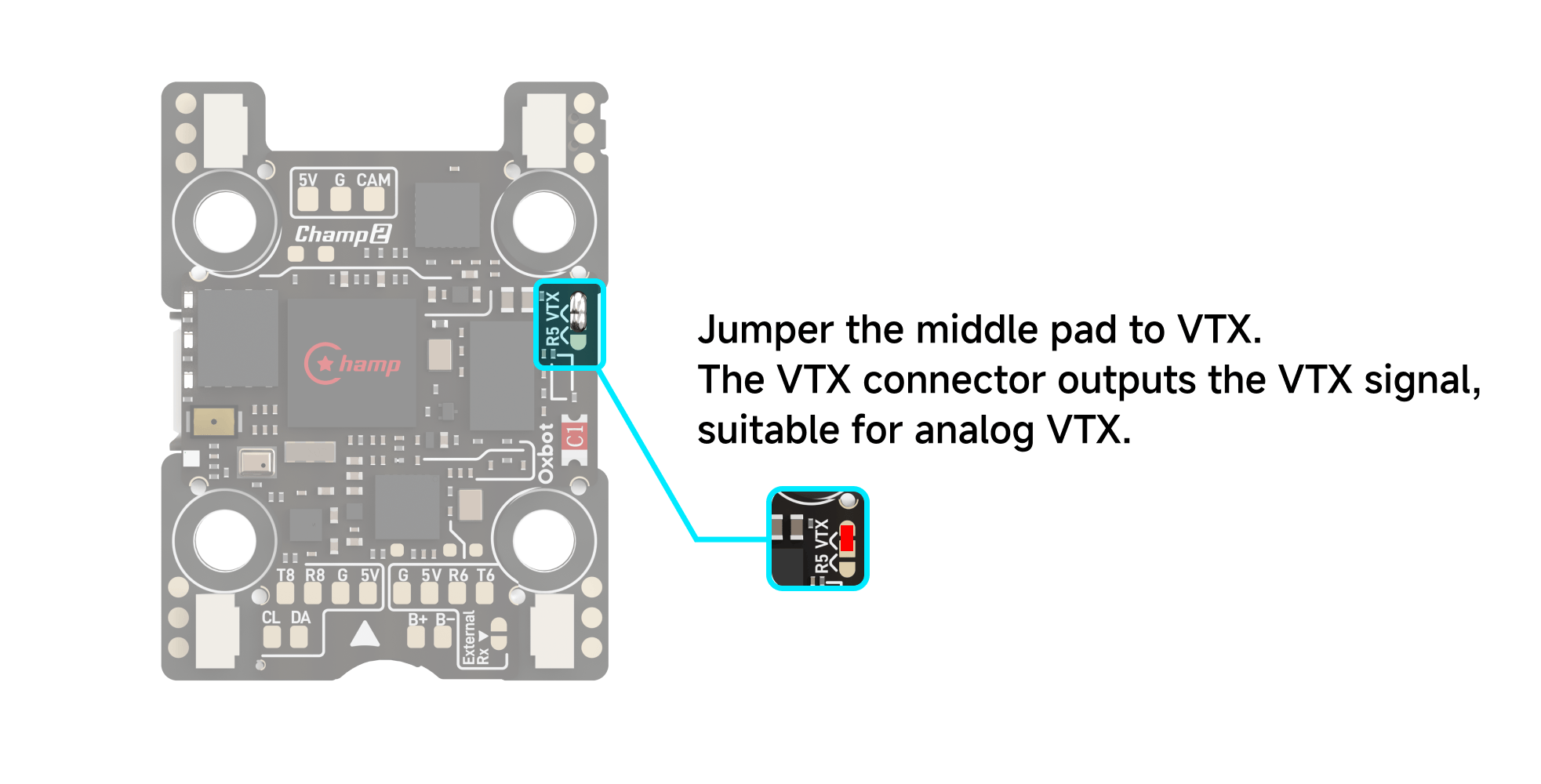
图传设置:VTX setup: 在 Betaflight【端口】页面关闭 UART5 的 MSP,并在对应外设栏选择 SmartAudio 或 IRC Tramp。设置完成后点击【保存并重启】。In the Betaflight Ports tab, disable MSP on UART5 and select SmartAudio or IRC Tramp in the related peripheral field. Click Save and Reboot when finished.
在 CLI 页面输入以下命令:Enter the following commands in the CLI:
set osd_displayport_device = MAX7456
set vcd_video_system = NTSC
save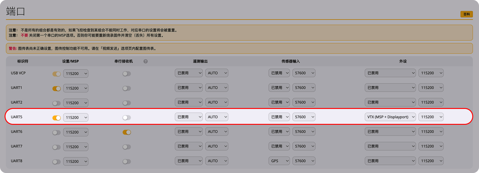
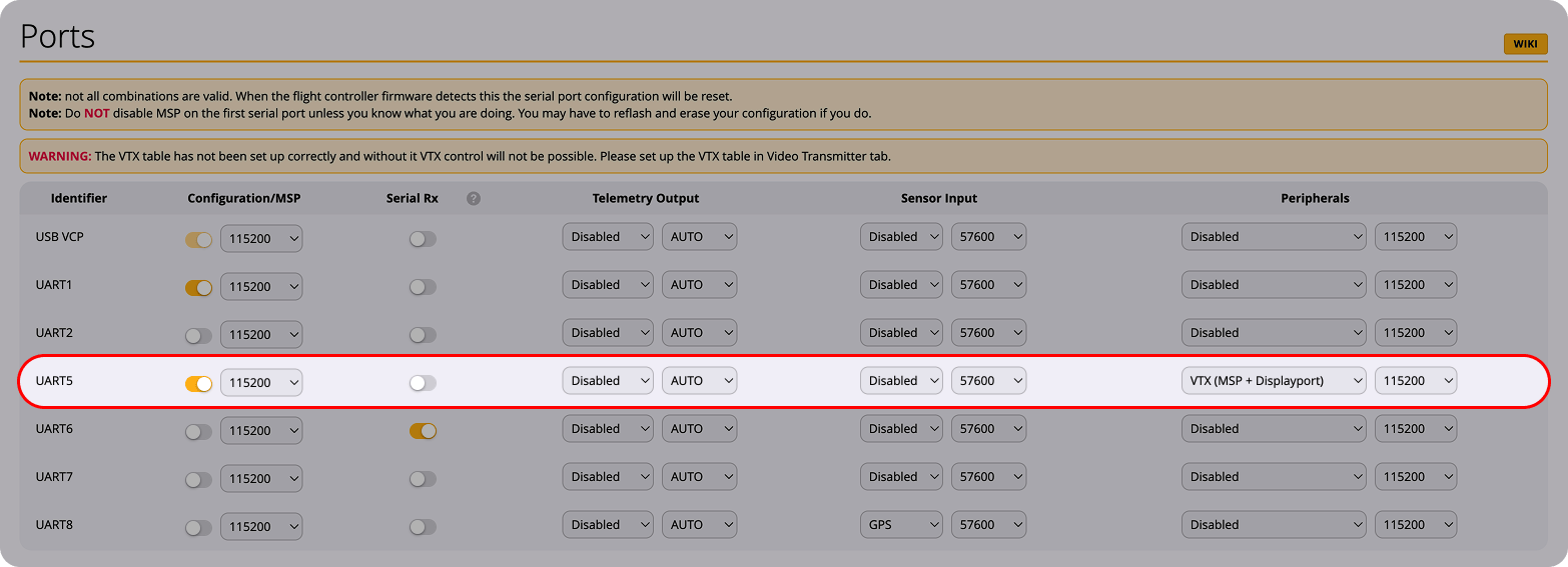
提示:Tip: 如使用 PAL 制式摄像头,请将第二条命令改为 set vcd_video_system = PAL。If you are using a PAL camera, change the second command to set vcd_video_system = PAL.
宽电压输入模拟图传Wide-Voltage Analog VTX
接线指引:Wiring: 可使用随包附带的 4P 图传排线连接模拟图传。飞控端插入图传接口,图传端按 VIN、GND、DATA、VTX 顺序焊接或插接。不同图传线序可能不同,焊接前必须核对图传丝印和线序。飞控同时保留图传焊盘,也可通过焊接方式连接。Use the included 4-pin VTX cable to connect the analog VTX. Plug the FC side into the VTX connector, then solder or plug the VTX side in the order of VIN, GND, DATA, and VTX. Wire order varies between VTX models, so always verify the silkscreen and pinout before soldering. The FC also keeps dedicated VTX pads for direct soldering if needed.
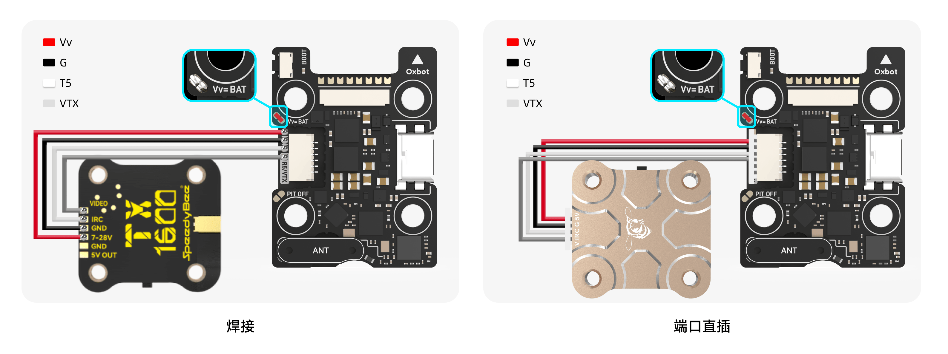
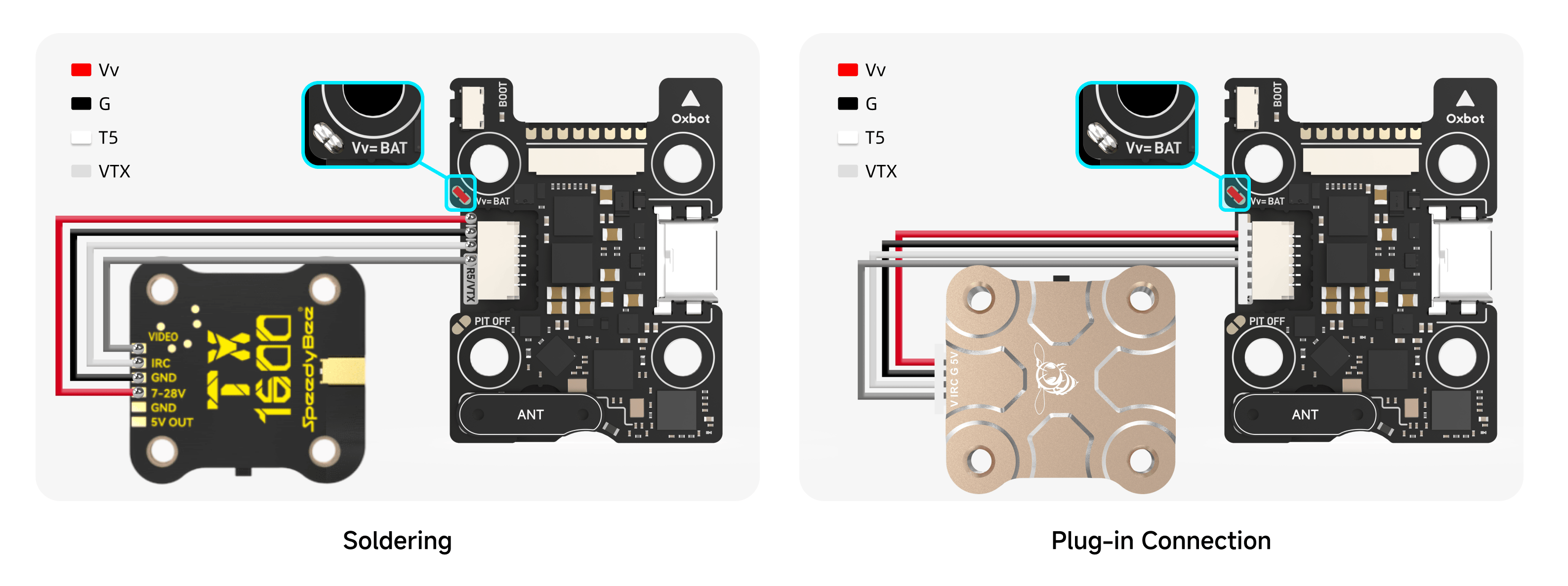
图传设置:VTX setup: 在 Betaflight【端口】页面关闭 UART5 的 MSP,并在对应外设栏选择 SmartAudio 或 IRC Tramp。设置完成后点击【保存并重启】。In the Betaflight Ports tab, disable MSP on UART5 and select SmartAudio or IRC Tramp in the related peripheral field. Click Save and Reboot when finished.
在 CLI 页面输入以下命令:Enter the following commands in the CLI:
set osd_displayport_device = MAX7456
set vcd_video_system = NTSC
save提示:Tip: 如使用 PAL 制式摄像头,请将第二条命令改为 set vcd_video_system = PAL。If you are using a PAL camera, change the second command to set vcd_video_system = PAL.
4. 模拟摄像头2.4.5 Analog Camera
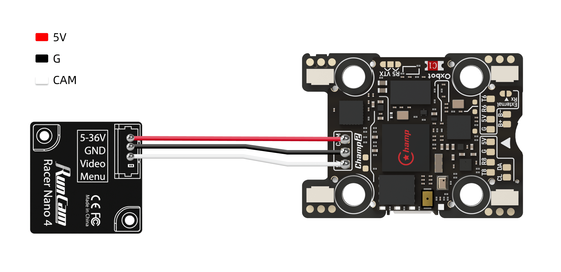
模拟摄像头请连接到飞控的 5V、GND 和 CAM 输入焊盘。Connect the analog camera to the 5V, GND, and CAM input pads on the FC.
5. 蜂鸣器、GPS 与其他串口2.4.6 Buzzer, GPS & UARTs
蜂鸣器Buzzer
将蜂鸣器正极连接到 BZ+,负极连接到 BZ-。焊接完成后请检查正负极是否接反。Connect the buzzer positive lead to BZ+ and the negative lead to BZ-. After soldering, double-check that polarity is correct.
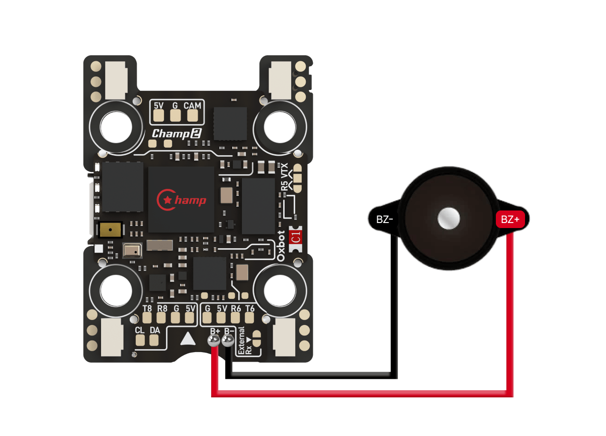
飞控设置:FC setup: 在 Betaflight【模式】页面添加 BEEPER 模式,并分配遥控器开关。保存后,拨动对应开关即可触发蜂鸣器。Add the BEEPER mode in the Betaflight Modes tab and assign it to a switch on your radio. After saving, toggling that switch will trigger the buzzer.


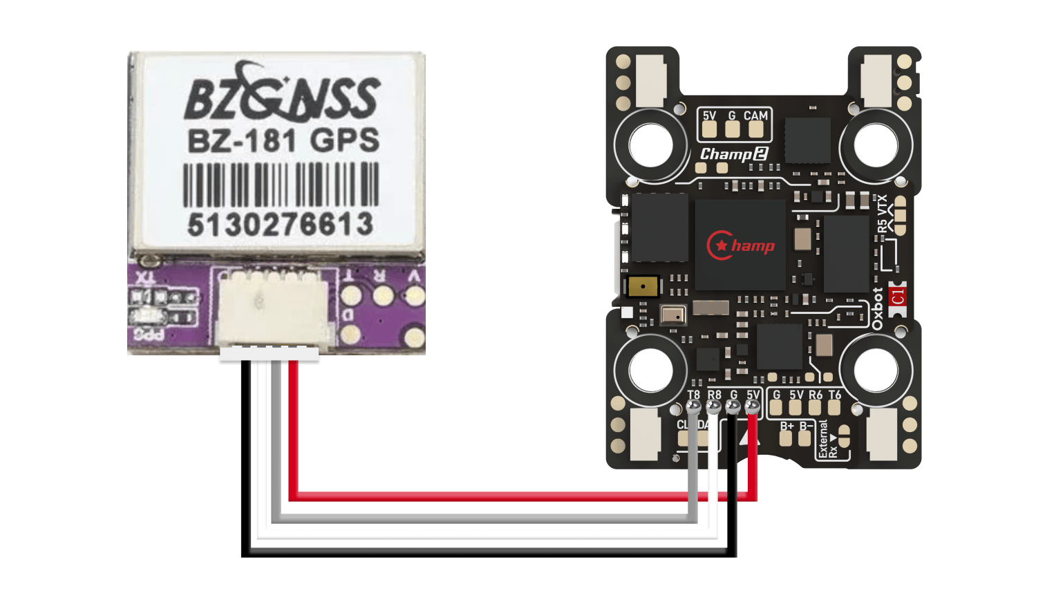
普通 GPSStandard GPS
仅连接 5V、GND、TX 和 RX。注意 GPS 的 TX 需要连接飞控 RX,GPS 的 RX 需要连接飞控 TX。Connect only 5V, GND, TX, and RX. Note that GPS TX must go to the FC RX pad, and GPS RX must go to the FC TX pad.
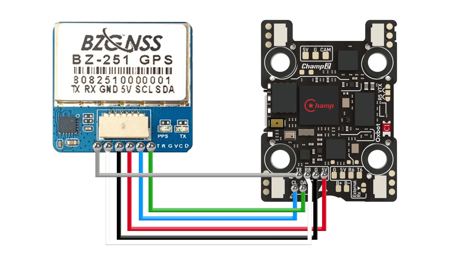
带磁力计 GPSGPS with Compass
GPS 的 TX 连接飞控 RX,GPS 的 RX 连接飞控 TX;磁力计线连接到对应的 SDA / SCL 接口。Connect GPS TX to the FC RX pad and GPS RX to the FC TX pad; connect the compass wires to the matching SDA / SCL pads.
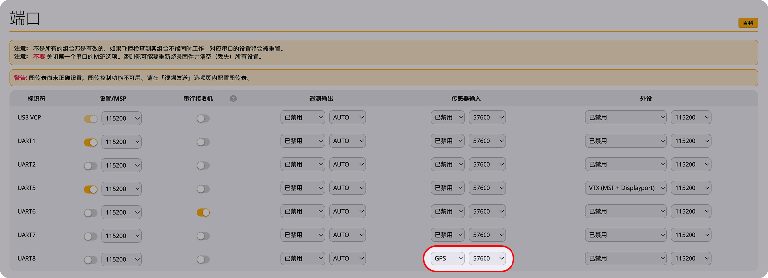
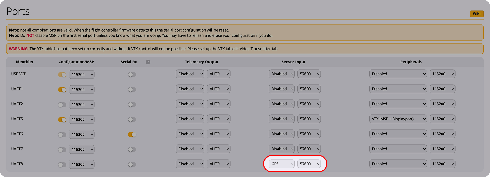
GPS 设置:GPS setup: GPS 出厂预设连接到 UART8。请在 Betaflight【端口】页面,将 UART8 的 Sensor Input 设置为 GPS,并在【GPS】页面开启 GPS 功能。The GPS is assigned to UART8 by default. In the Betaflight Ports tab, set the Sensor Input on UART8 to GPS, then enable GPS in the GPS tab.
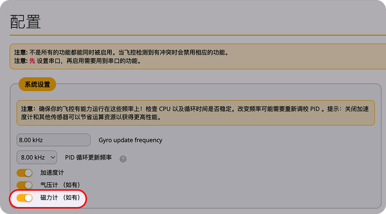
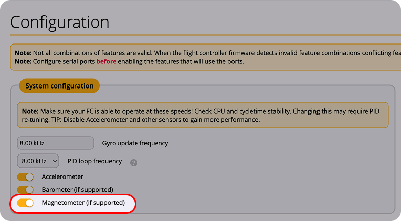
如果 GPS 有内置磁力计,可以在配置中打开磁力计功能。If the GPS includes a built-in compass, you can also enable the compass feature in the configuration.
五、APP 连接2.5 App Connection
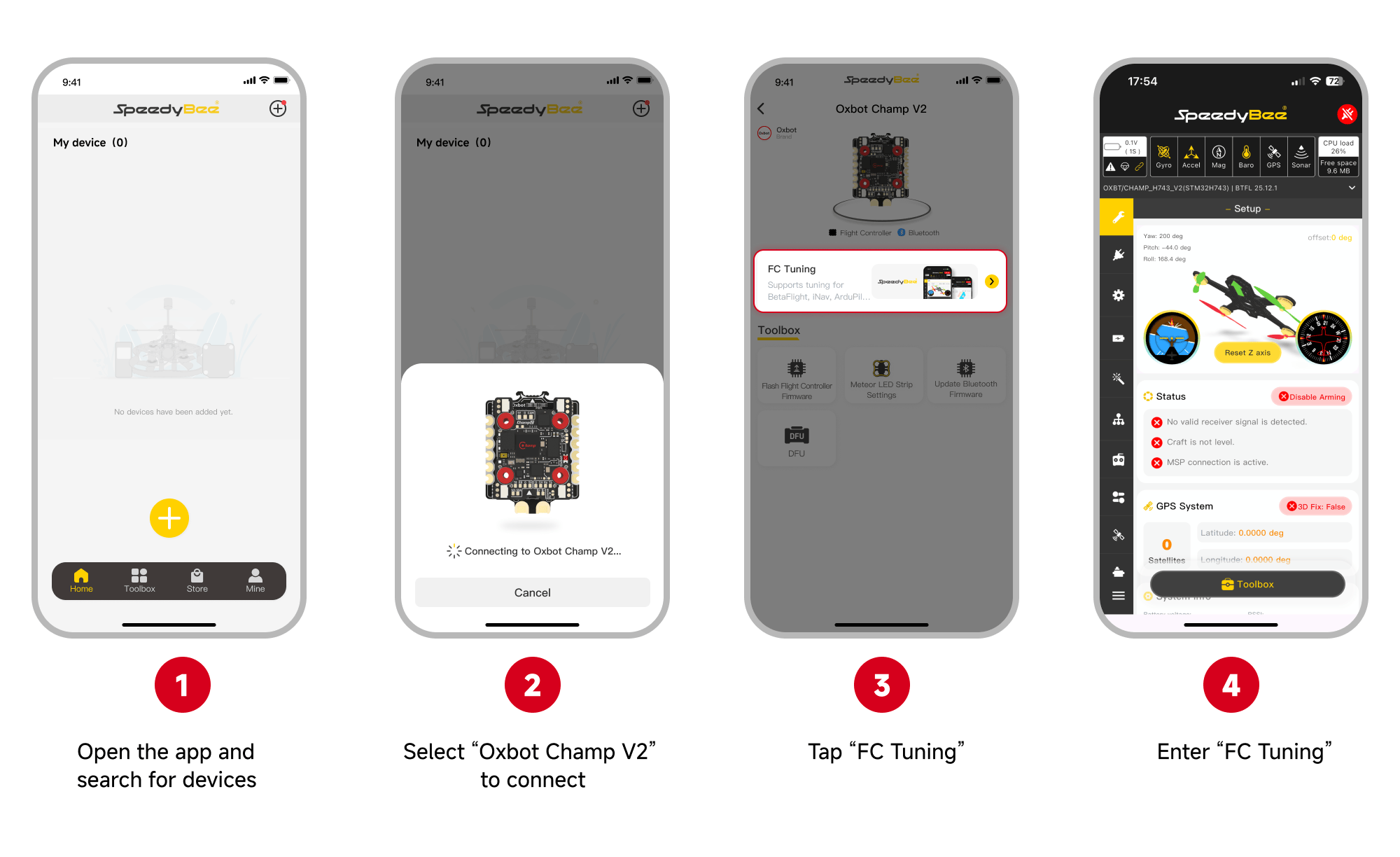
CHAMP 2 飞控支持通过 SpeedyBee / 快蜂 App 连接,用于查看飞控状态、进入飞控调参页面以及修改部分飞控参数。The CHAMP 2 flight controller supports connection through the SpeedyBee app for status monitoring, entering FC tuning pages, and changing selected FC parameters.
操作步骤:Steps:
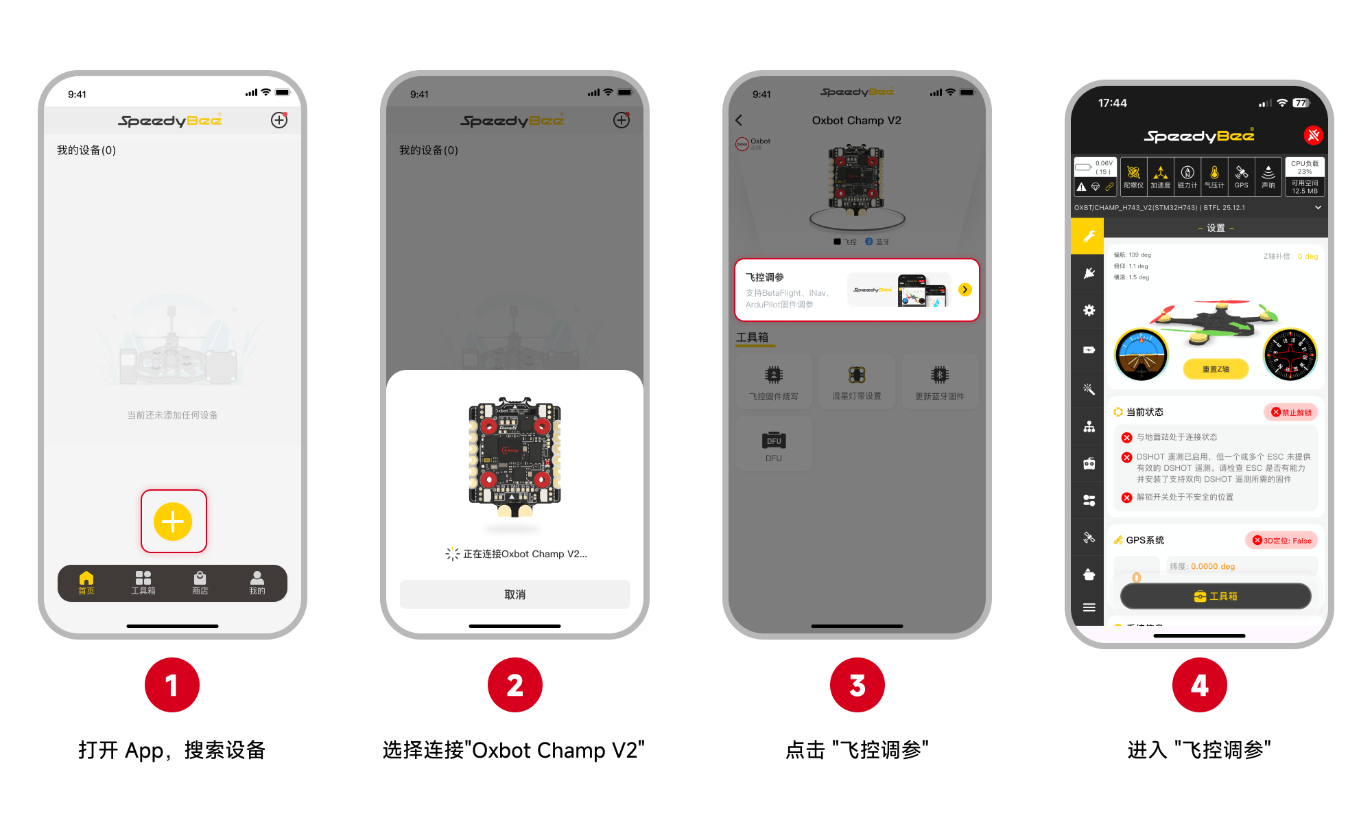
- 打开 SpeedyBee / 快蜂 App,点击搜索设备。Open the SpeedyBee app and tap to search for devices.
- 在设备列表中选择 "Oxbot Champ 2",点击 "立即连接"。Select "Oxbot Champ 2" from the device list, then tap "Connect Now".
- 进入飞控页面后,点击 "飞控调参",即可进入参数设置页面。After entering the FC page, tap "FC Tuning" to open the parameter setup page.
六、飞控固件更新2.6 Firmware Update
CHAMP 2 飞控使用 Betaflight 固件,固件目标名称为 CHAMP_H743_V2。在固件尚未加入 Betaflight 在线固件列表前,请使用官方提供的本地固件文件进行刷写。The CHAMP 2 FC uses Betaflight firmware with the target name CHAMP_H743_V2. Before this target appears in the Betaflight online firmware list, please flash it using the official local firmware file.
- 请先备份当前 Betaflight 配置;Back up your current Betaflight configuration first.
- 请使用支持数据传输的 USB 数据线;Use a USB data cable that supports data transfer.
- 刷写过程中请勿断开 USB 连接;Do not disconnect USB during the flashing process.
- 请确认选择的固件文件与飞控型号 CHAMP_H743_V2 匹配。Confirm the firmware file matches the CHAMP_H743_V2 FC target.
操作步骤:Steps:
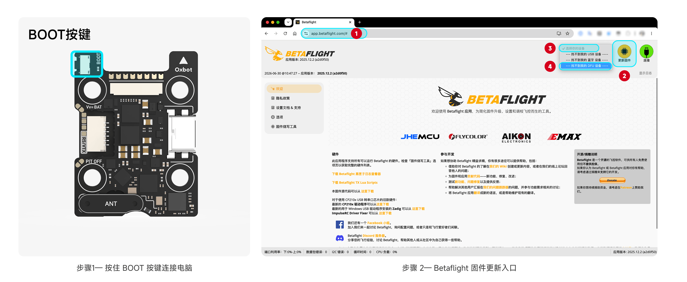
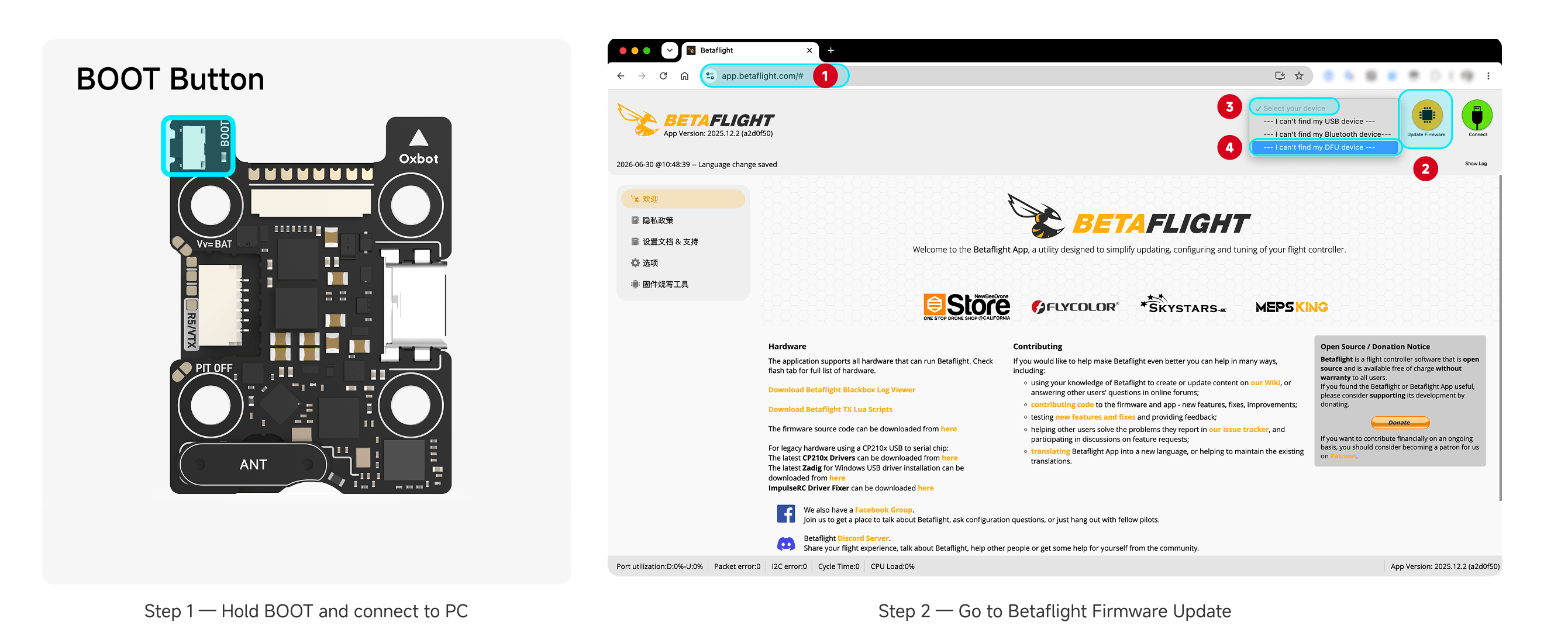
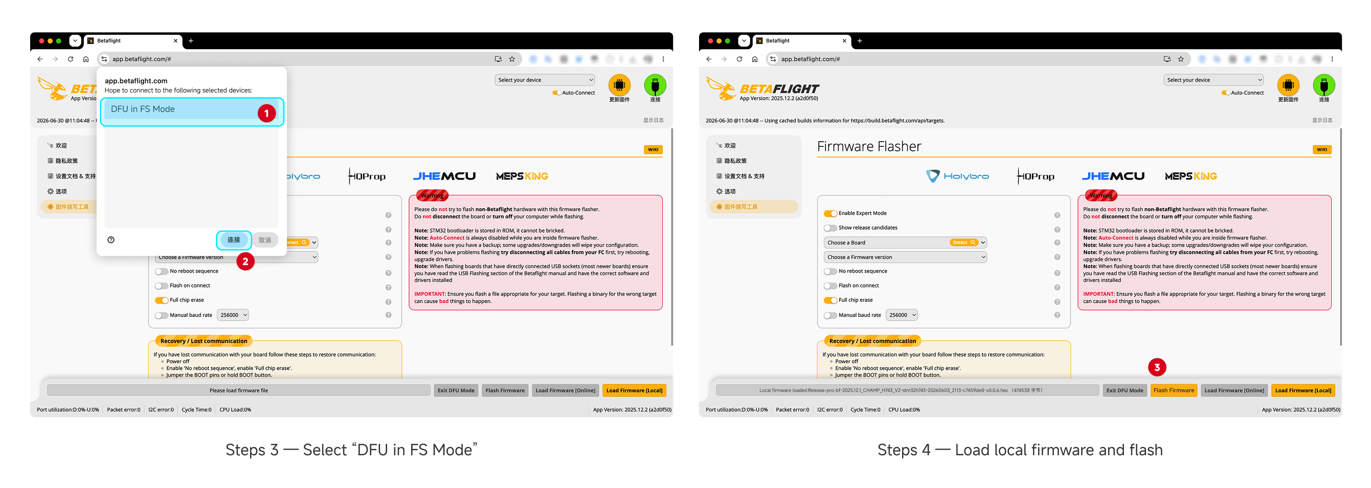
- 按住飞控 BOOT 按键后,将飞控通过 USB 连接到电脑。Hold the BOOT button on the FC, then connect the FC to the computer via USB.
- 打开 Betaflight Configurator 或 Betaflight Web App,点击上方的固件更新按钮。Open Betaflight Configurator or Betaflight Web App and click the firmware update button at the top.
- 如果无法直接识别 DFU 设备,请选择 "找不到我们的 DFU 设备"。If the DFU device is not detected directly, choose "Unable to find our DFU device".
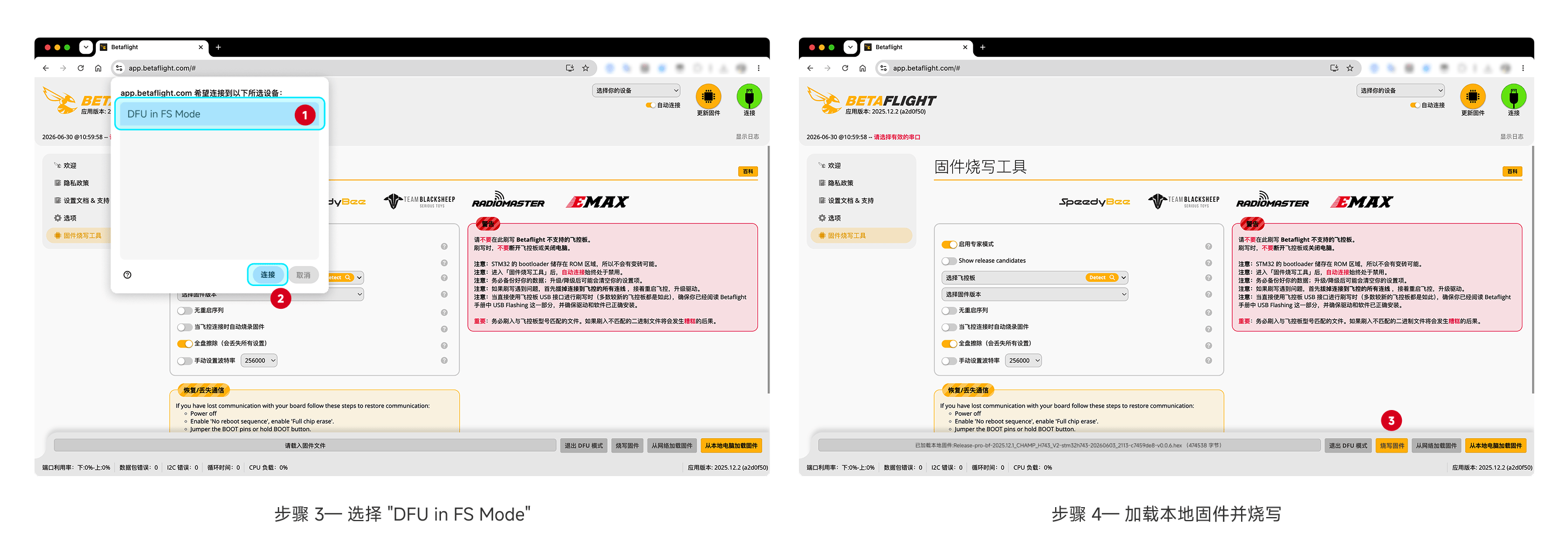
- 在弹出的设备列表中选择 "DFU in FS Mode",并点击连接。连接后,上方会显示飞控对应的 DFU 端口。Select "DFU in FS Mode" in the pop-up device list and connect. After connection, the matching DFU port for the FC will appear at the top.
- 由于当前固件暂时无法从 Betaflight 在线列表下载,请选择 "从本地电脑加载固件"。Because this firmware is not yet available from the Betaflight online list, choose "Load firmware [Local]".
- 选择本地固件文件后,点击 "烧写固件",等待进度条完成。Select the local firmware file, click "Flash Firmware", and wait for the progress bar to complete.
- 刷写完成后,重新连接飞控,并检查固件版本、端口、接收机、图传、OSD、GPS 等设置是否正常。After flashing, reconnect the FC and verify the firmware version, ports, receiver, VTX, OSD, GPS, and other settings.
CHAMP_H743_V2_2025.12.1_20260603.hex
七、飞控参数表2.7 FC Parameters
表 2-3 CHAMP 2 飞控参数表Table 2-3 CHAMP 2 flight controller parameters
| 项目Item | 参数Specs |
|---|---|
| 产品名称Product Name | Oxbot Champ 2 飞控Oxbot Champ 2 flight controller |
| 主控MCU | STM32H743 |
| 陀螺仪Gyro | MPU6000版本 / ICM42688版本MPU6000 version / ICM42688 version |
| 完整版说明书链接Full Manual Link | https://oxbot.cn/download-center.html |
| 内置接收机Built-in Receiver | ELRS 2.4G 固件名称:Oxbot 2.4GHz RXELRS 2.4G Firmware name: Oxbot 2.4GHz RX |
| USB接口类型USB Port Type | Type-C |
| 气压计Barometer | 支持Supported |
| OSD芯片OSD Chip | AT7456 |
| 蓝牙BLEBluetooth BLE | 支持,用于连接快蜂SpeedyBee App进行飞控的参数设置。务必确保串口UART 1的MSP开关打开,并设置波特率为115200,否则无法使用蓝牙功能。Supported for connecting to the SpeedyBee app for FC setup. Make sure MSP is enabled on UART1 and the baud rate is set to 115200, otherwise BLE will not work. |
| WiFi | 不支持Not supported |
| 图传连接方式Digital VTX Connection | 6pin插座直插。与DJI O4/DJI O3/RunCam Link/Caddx Vista/DJI Air Unit完全兼容,可通过跳线焊盘兼容模拟图传。Direct plug-in 6-pin connector. Fully compatible with DJI O4, DJI O3, RunCam Link, Caddx Vista, and DJI Air Unit. Analog VTX is supported through the jumper pads. |
| HDZero图传连接方式HDZero VTX Connection | 6pin插座。请注意HDZero 图传新旧版本线序6-pin connector. Pay attention to the wire order differences between older and newer HDZero VTX versions. |
| 黑匣子Blackbox | 内置16 MB黑匣子芯片Built-in 16MB Blackbox chip |
| 电流计Current Sensor | 无Not available |
| 输入电压Input Voltage | 3~8S |
| BEC输出BEC Output | 5V 3.5A |
| 电调信号线ESC Signal Outputs | M1-M4 |
| 空闲UART串口Available UARTs | UART5, UART6, UART7,UART8UART5, UART6, UART7, UART8 |
| 电调遥测输入ESC Telemetry Input | UART2 |
| Betaflight 摄像头调参焊盘 (CC)Betaflight Camera Control Pad (CC) | 不支持Not supported |
| GPS焊盘GPS Pads | 支持Supported |
| I2C | 支持Supported |
| LED焊盘LED Pads | 支持,四路并联Supported, four outputs in parallel |
| 蜂鸣器焊盘Buzzer Pads | 支持,5V有源蜂鸣器Supported, 5V active buzzer |
| PIT模式PIT Mode | 支持Supported |
| BOOT键BOOT Button | 支持,按住BOOT键通电开机,可进入DFU模式,用于飞控出现问题时刷写固件。此按键同时用于LED灯带控制。(详见:LED 灯带 > 流星灯效设置)Supported. Hold the BOOT button while powering up to enter DFU mode for firmware recovery or flashing. This button is also used for LED strip control. (See 2.4.2 Meteor Effects.) |
| 支持的飞控固件类型Supported FC Firmware | BetaFlight (默认出厂固件)Betaflight (factory default firmware) |
| 固件名称Firmware Target | CHAMP_H743_V2 两个陀螺仪版本通用CHAMP_H743_V2, shared by both gyro versions |
| 安装孔位Mounting Pattern | 20 x 20mm (M3) |
| 尺寸Dimensions | 28*37.5*5.35MM |
| 重量Weight | 7.8g |
Part 3 / 电调Part 3 / ESC
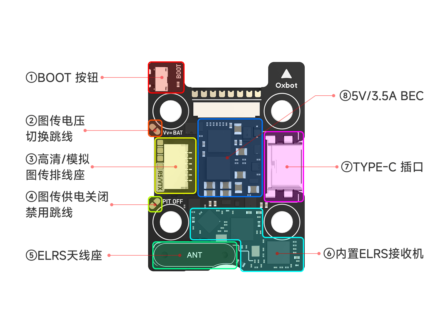
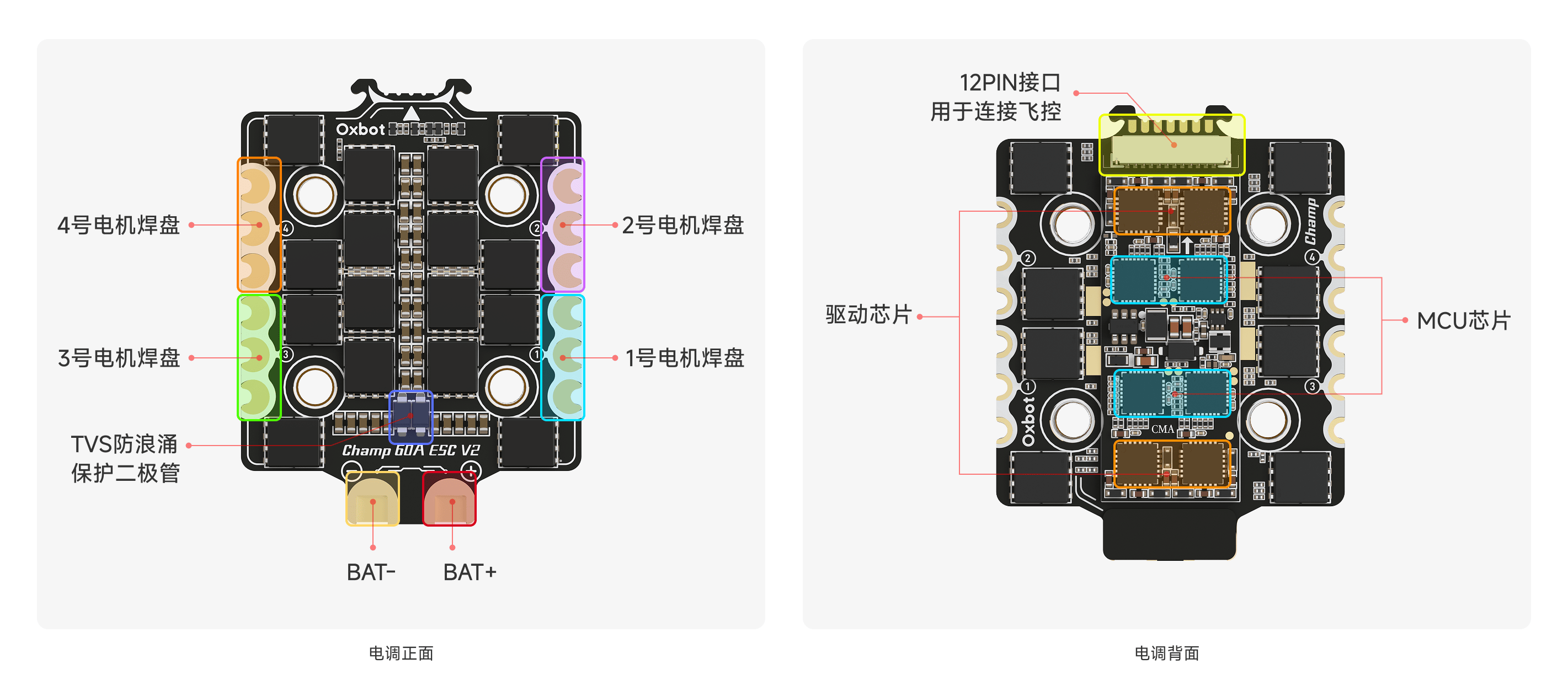
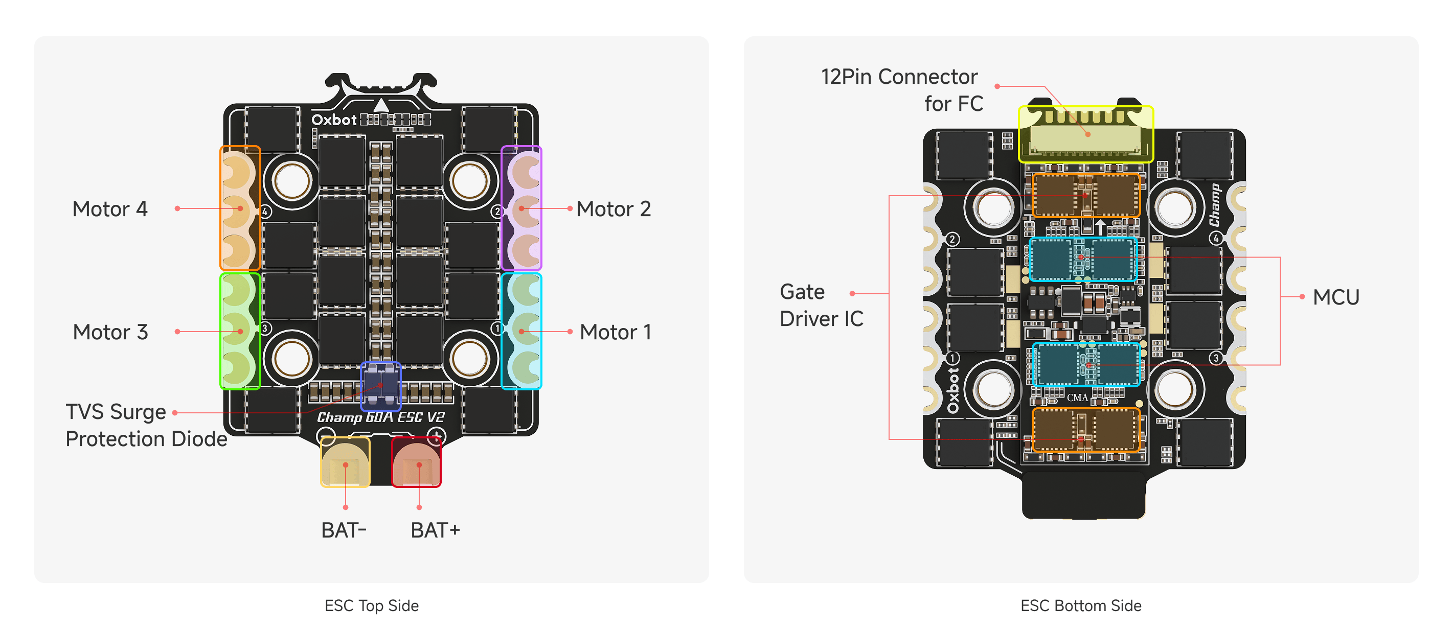
一、外观说明3.1 Appearance
二、飞控、电调与电机连接3.2 FC / ESC / Motor Connection
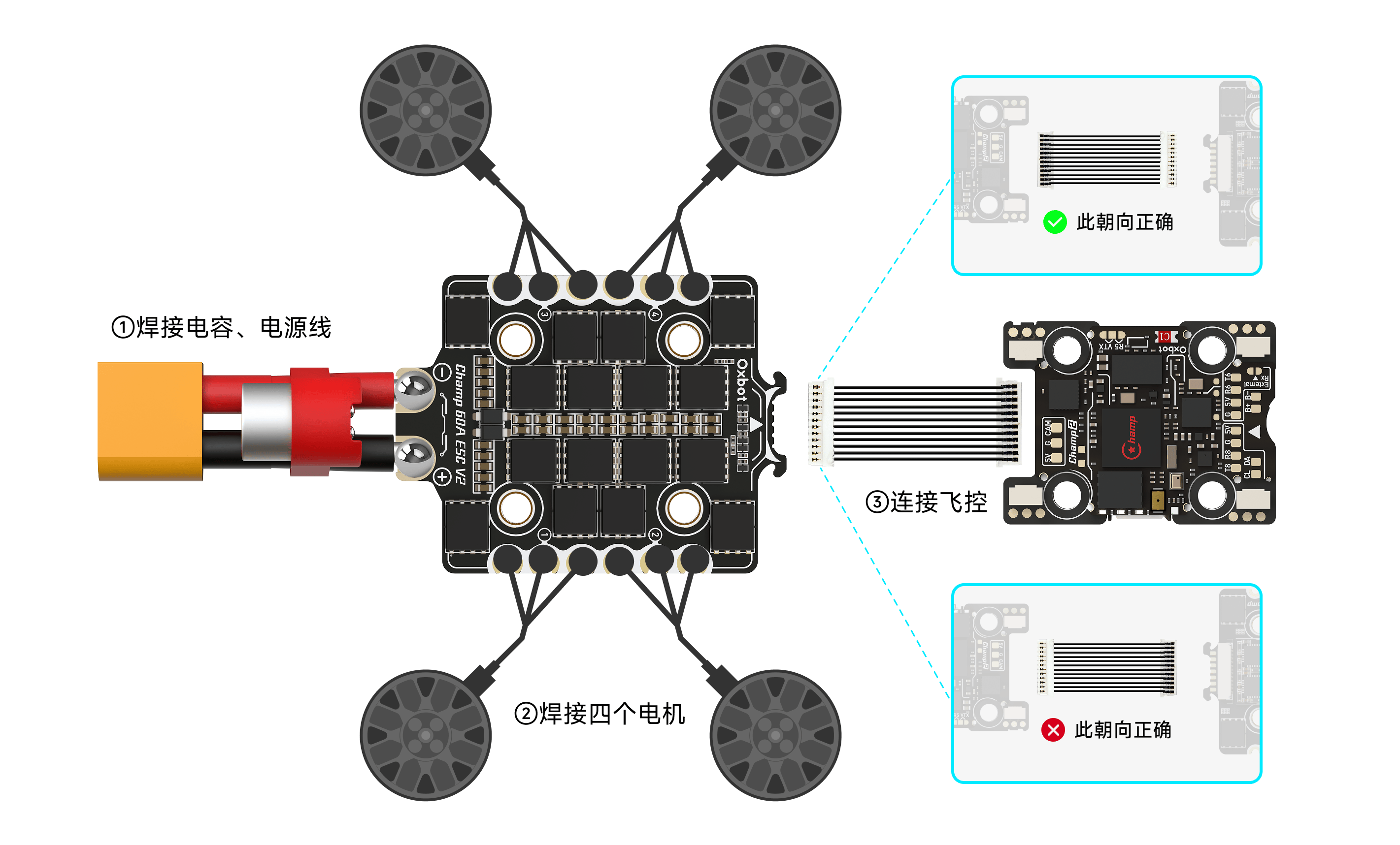
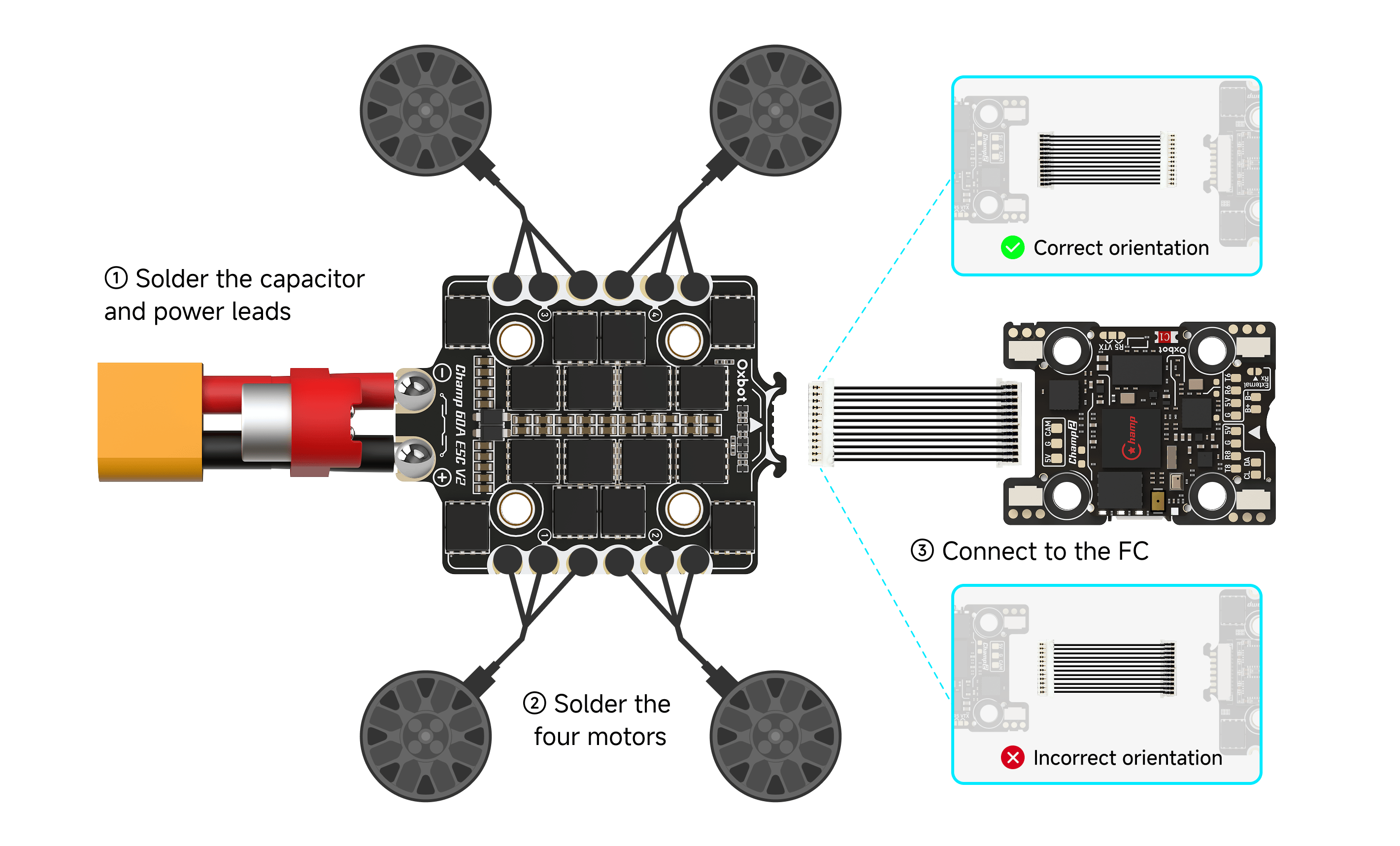
飞控与电调可通过原装排线连接,也可通过焊盘焊接连接。推荐优先使用原装排线。若使用焊接方式,请严格按照焊盘定义连接,并在上电前检查短路。The FC and ESC can be connected either with the original cable or by soldering pads directly. The original cable is recommended whenever possible. If you use solder joints, follow the pad definition exactly and check carefully for shorts before powering up.
三、电调调参与固件更新3.3 ESC Tuning & Firmware Update
(一)连接地面站并调参3.3.1 Connect Ground Station & Tune
- 拆下所有桨叶。Remove all propellers.
- 使用电池为飞塔供电,并通过 USB 数据线将飞控连接到电脑。电调调参或刷写时需要电池供电,仅 USB 供电无法给电调供电。Power the stack from a battery and connect the FC to the computer with a USB cable. Battery power is required for ESC tuning or flashing; USB alone will not power the ESC.
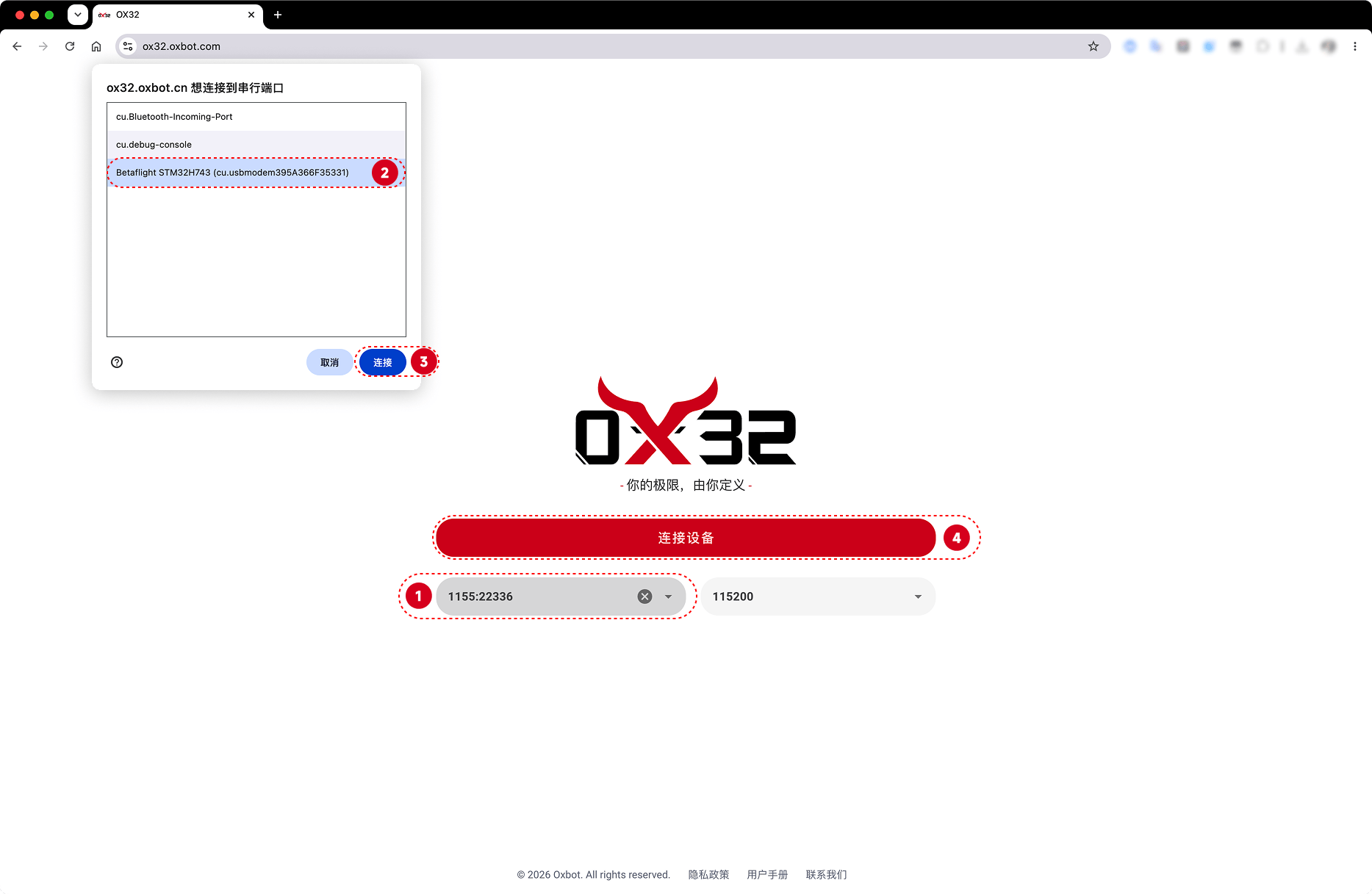
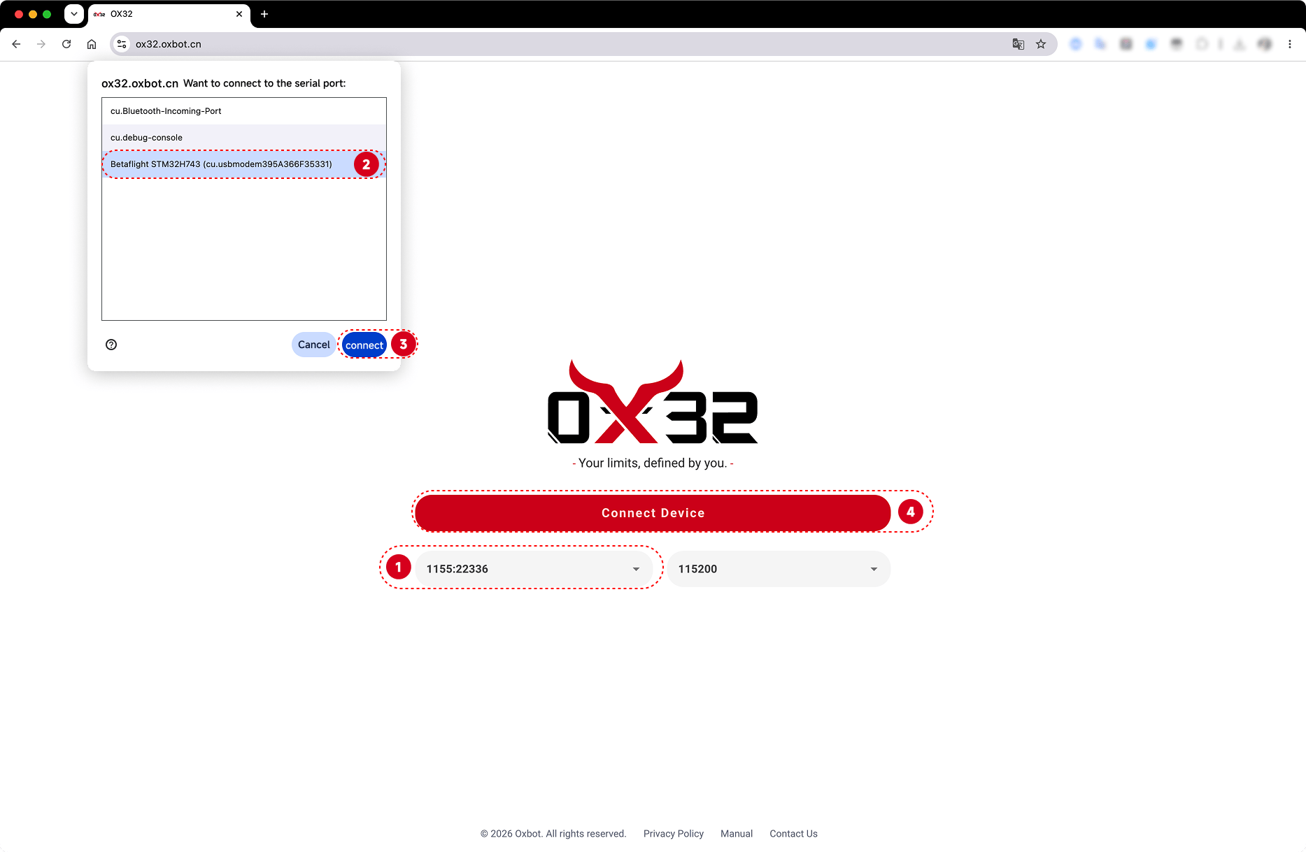
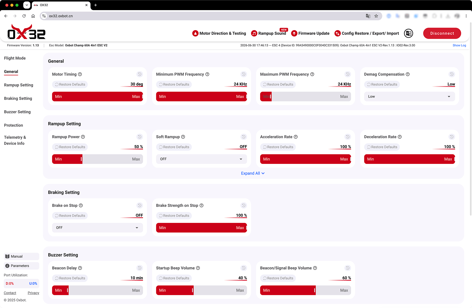
- 打开 OX32 电调地面站,进入 https://ox32.oxbot.cn,点击【连接设备】。Open the OX32 ESC configurator at https://ox32.oxbot.com, then click Connect Device.
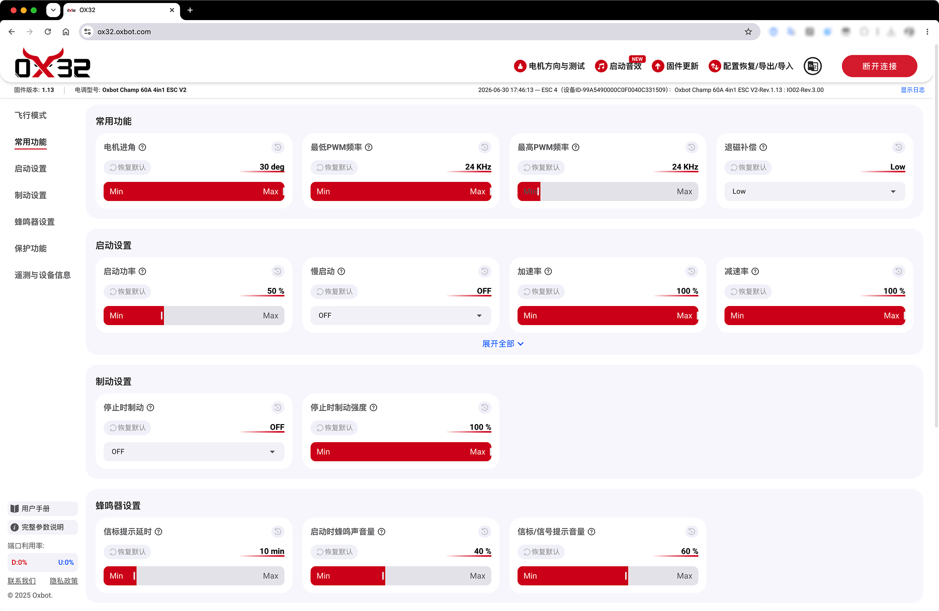
- 连接成功后,建议先读取并保存当前参数,再根据需要修改电机方向、PWM 频率、启动功率等参数。修改完成后点击写入/保存,并重新上电验证。After connecting successfully, read and save the current setup first, then adjust parameters such as motor direction, PWM frequency, and startup power as needed. Click write / save when done, then power-cycle and verify.
(二)电调固件更新3.3.2 ESC Firmware Update
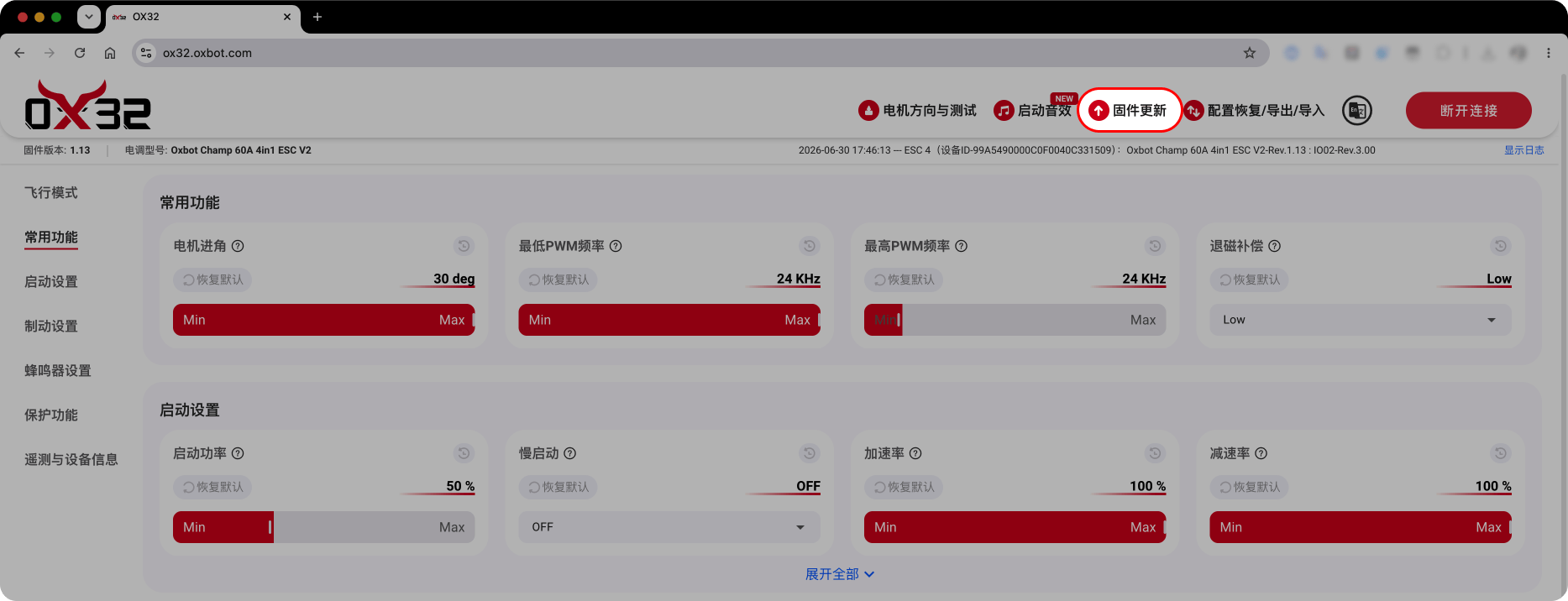
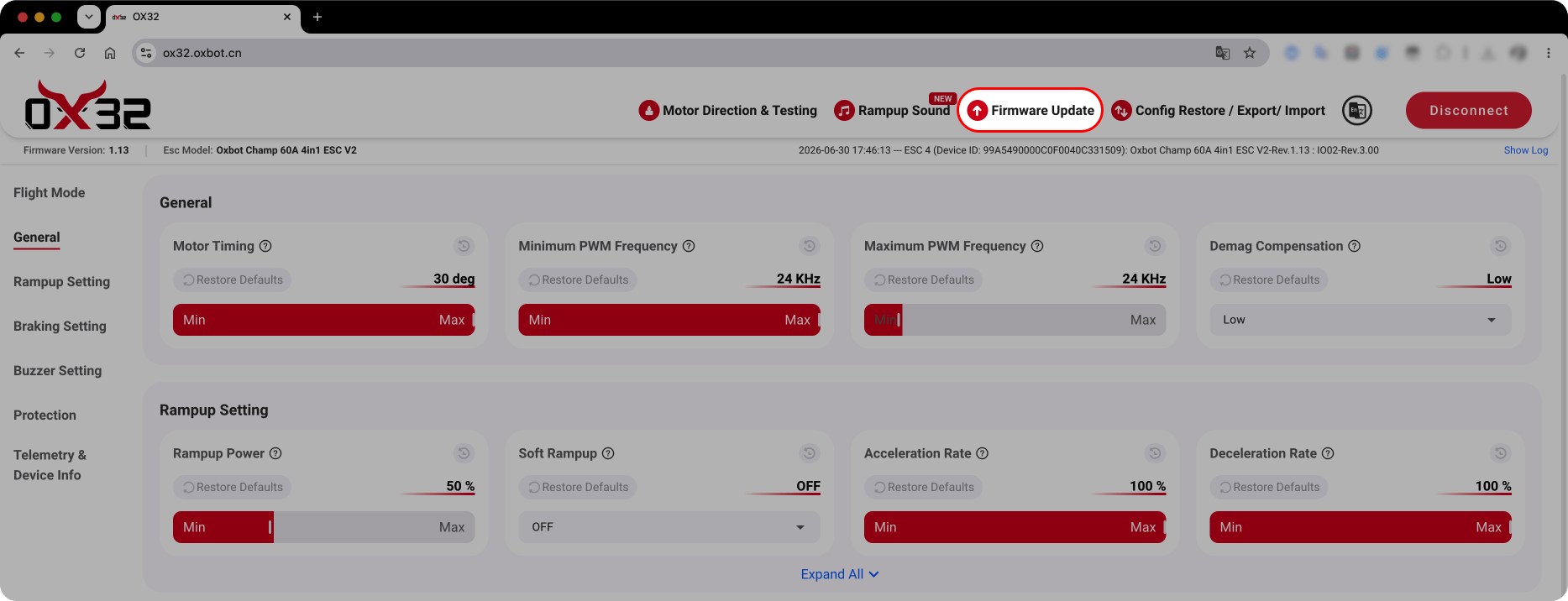
连接地面站成功后,点击【固件更新】,即可更新电调固件。After connecting to the configurator, click Firmware Update to update the ESC firmware.
(三)飞行模式切换3.3.3 Flight Mode Switching
OX32 电调提供四种飞行模式预设(标准竞速 / Ultra竞速 / 花飞 / 远航),可通过 OX32 Configurator 一键切换电机进角、PWM 频率和退磁补偿等核心参数,无需逐项手动调整。OX32 ESC offers four preset flight modes (Standard Racing / Ultra Racing / Freestyle / Long Range). You can switch core parameters like motor timing, PWM frequency, and demag compensation with a single click using the OX32 Configurator, with no need to adjust them manually one by one.
操作步骤:Steps:
- 点击左侧导航栏「飞行模式」,弹出预设选择窗口。Click "Flight Mode" on the left navigation bar to open the preset selection window.
- 会出现四种模式卡片,点击下方的「使用该模式」按钮。Four mode cards will appear. Click the "Use this mode" button at the bottom.
- 核对确认对话框中的参数列表,点击红色「确认」按钮写入电调。Review and confirm the parameters list in the dialog, then click the red "Confirm" button to write them to the ESC.
- 提示「保存成功」即完成模式切换。The system will display "Saved successfully" to complete the switch.
四、电调参数表3.4 ESC Parameters
表 3-1 CHAMP 2 电调参数表Table 3-1 CHAMP 2 ESC parameters
| 项目Item | 参数Specs |
|---|---|
| 产品名称Product Name | Oxbot Champ 2 四合一竞速电调Oxbot Champ 2 4-in-1 racing ESC |
| 固件Firmware | OX32固件OX32 firmware |
| 电脑端地面站链接PC Configurator Link | https://ox32.oxbot.cnhttps://ox32.oxbot.com |
| 持续电流Continuous Current | 每路60A60A per channel |
| 最大电流Peak Current | 每路80A (10秒)80A per channel (10 seconds) |
| 单路最大电流(仅一路电机转动)Single-Channel Max Current (one motor only) | 110A (10 seconds) |
| 内置TVS防浪涌瞬态抑制二极管Built-in TVS Surge Suppression Diode | 是Yes |
| 外置电容External Capacitor | 35V 470uF固态电容 (包装内附)35V 470uF solid capacitor (included in the package) |
| ESC/电机协议ESC / Motor Protocol | DSHOT300/600 |
| 输入电压Input Voltage | 3-8S锂离子电池3-8S LiPo battery |
| 输出电压Output Voltage | VBAT |
| 电流计Current Sensor | 不支持Not supported |
| 电调遥测ESC Telemetry | 支持Supported |
| 安装孔位Mounting Pattern | 20 x 20mm (M3) |
| 尺寸Dimensions | 35.5*46.46*4.75 |
| 重量Weight | 16.5g |
Part 4 / 首次使用检查Part 4 / Pre-flight Check
- 焊接检查:Solder inspection: 确认所有焊点无短路、无虚焊。特别注意飞控或电调表面是否有焊接时溅出的锡珠。初次连接电池时建议连接短路保护器再上电。Confirm there are no shorts or cold joints on any solder point. Pay special attention to solder balls left on the FC or ESC after soldering. For the first battery connection, it is recommended to use a smoke stopper.
- 电机转向:Motor direction: 拆下桨叶,接通电池和 USB,在 Betaflight【电机】页面逐个测试电机转向。如方向错误,可使用Betaflight地面站的电机转向功能进行更改。Remove all props, connect battery and USB, then test each motor direction in the Betaflight Motors tab. If a motor spins the wrong way, change it using the motor direction function in Betaflight.
- 飞控方向:FC orientation: 在 Betaflight【设置】页面倾斜飞塔,确认 3D 模型与实际运动方向一致。Tilt the stack in the Betaflight Setup tab and confirm the 3D model follows the real movement correctly.
- 遥控器通道:Radio channels: 在 Betaflight【接收机】页面检查各通道映射和行程是否正确。Check channel mapping and endpoint travel in the Betaflight Receiver tab.
- 模式开关:Mode switches: 确认解锁(ARM)、自稳(ANGLE)、蜂鸣器(BEEPER)、反乌龟(FLIP OVER AFTER CRASH)等模式开关功能正常。Verify that ARM, ANGLE, BEEPER, FLIP OVER AFTER CRASH, and other assigned switches work properly.
- 图传输出:Video output: 确认图传画面正常,无雪花或黑屏。OSD 元素显示完整。Confirm the video feed is normal with no static or black screen, and that all OSD elements display correctly.
- GPS(如有):GPS (if installed): 在室外空旷处等待 GPS 搜星锁定(3D Fix),确认坐标和返航点已保存。Wait in an open outdoor area for GPS lock (3D Fix), and confirm coordinates and home point have been recorded.
Part 5 / 常见问题排查Part 5 / Troubleshooting
飞控无法连接电脑FC Won't Connect to PC
请按以下步骤检查:Please check the following:
- 确认 USB 数据线支持数据传输,部分充电线仅支持充电,不支持数据通信。Make sure the USB cable supports data transfer. Some charging-only cables do not carry data.
- 尝试更换电脑 USB 端口或更换电脑。Try another USB port or a different computer.
- 检查飞控主控状态灯是否正常闪烁。Check whether the MCU status LED on the FC is blinking normally.
- 如果状态灯正常,但电脑仍无法识别飞控,可尝试使用 ImpulseRC Driver Fixer 修复驱动。If the LED is normal but the FC is still not detected, try repairing the driver with ImpulseRC Driver Fixer.
如修复驱动后仍无法连接,请联系售后支持。If the FC still cannot connect after repairing the driver, please contact after-sales support.
ImpulseRC_Driver_Fixer.exe
使用方法:按住飞控上的 BOOT 按键,然后插入飞控 USB,打开刚刚下载的 ImpulseRC,等待一段时间,直到提示驱动安装成功。How to use: hold the BOOT button on the FC, plug in the FC over USB, open the downloaded ImpulseRC tool, and wait until it reports a successful driver installation.
内置 ELRS 接收机无法对频Built-in ELRS Receiver Won't Bind
- 确认遥控器 / 高频头与接收机的对频短语设置一致;如果使用手动对频,请确认两端均未启用对频短语。Confirm the binding phrase on the radio / TX module matches the receiver. If binding manually, make sure binding phrase is disabled on both sides.
- 如果接收机 LED 连续快速闪烁三次,表示 Model Match 不匹配。请在遥控器 ELRS LUA 脚本中检查 Model Match 设置,确保模型 ID 一致,或关闭 Model Match 后重新对频。If the receiver LED flashes quickly three times, it indicates a Model Match mismatch. Check Model Match in the ELRS LUA script, make sure the model ID matches, or disable Model Match and bind again.
模拟图传没画面Analog VTX Has No Picture
请确认图传供电电压设置是否正确。CHAMP 2 飞控图传接口支持 5V 与 BAT(电池电压)两种供电方式,具体请参考图传章节。Confirm that the VTX power voltage is set correctly. The CHAMP 2 FC supports both 5V and BAT (battery voltage) output on the VTX port. See the VTX section for details.
请确认高清 / 模拟图传切换跳线是否设置正确。飞控默认信号为 R5(高清图传)。如果使用模拟图传,需要将信号切换至 VTX。Also confirm that the HD / analog signal jumper is set correctly. The FC defaults to R5 for digital video. If you are using analog video, switch the signal to VTX.
模拟图传OSD 无显示Analog VTX OSD Not Displayed
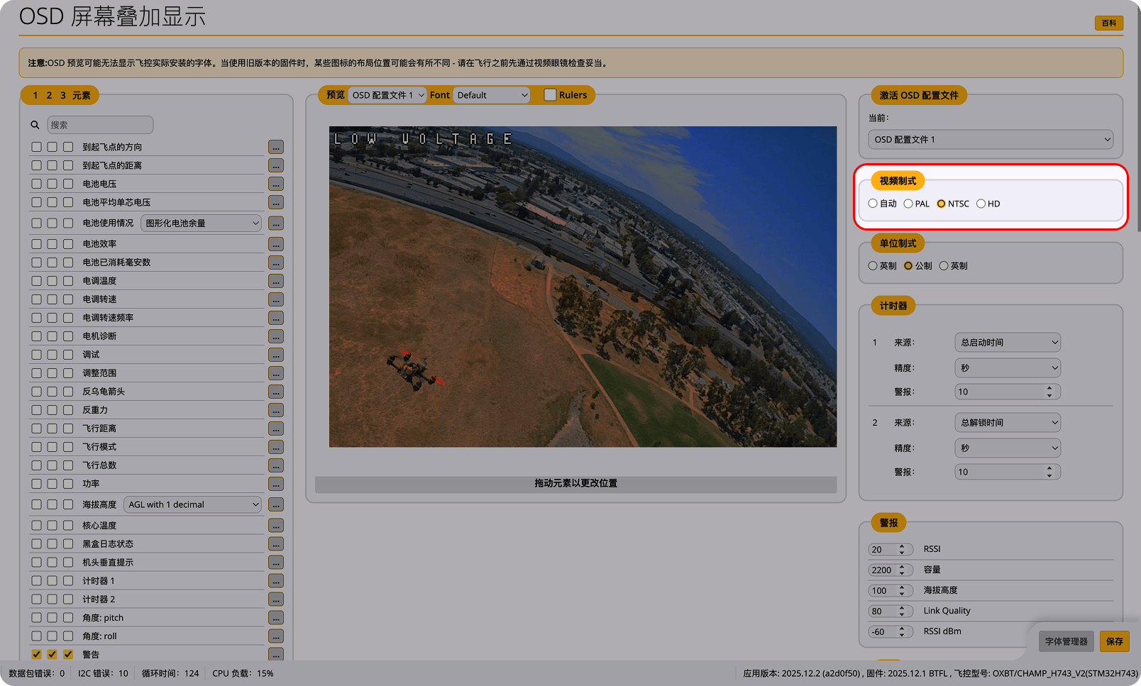
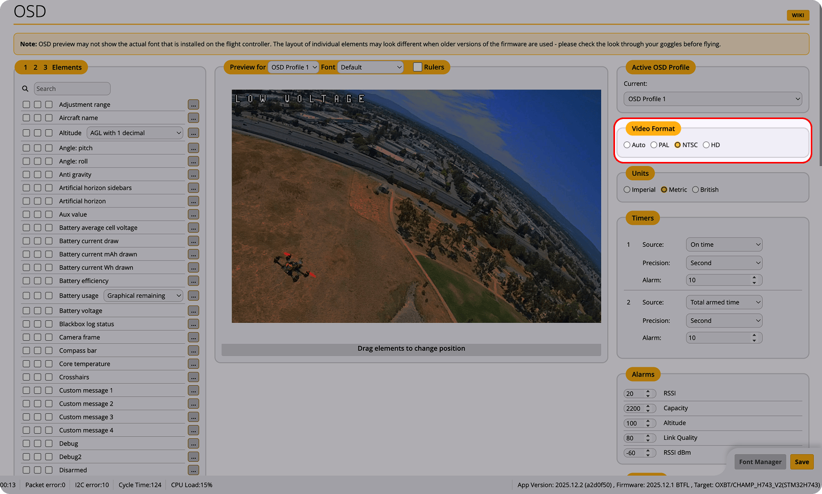
请先确认 OSD 输出模式和视频制式设置是否正确。如果接线和设置均正常,但 OSD 仍无法显示,请分别尝试 NTSC 与 PAL 视频制式,不建议直接使用 AUTO。First confirm the OSD output mode and video system are configured correctly. If wiring and settings are correct but OSD still does not appear, try NTSC and PAL manually. Do not rely on AUTO.
GPS /外置接收机在使用USB供电时无法工作GPS / External Receiver Won't Work on USB Power
这是正常现象。GPS 模块和部分外置接收机通常需要在连接电池供电后才能正常工作。仅连接 USB 时,相关外设可能不会上电或无法被飞控识别。This is normal. GPS modules and some external receivers usually require battery power to work correctly. With USB power only, those peripherals may not power up or may not be detected by the FC.
GPS 无法搜星GPS Can't Get Satellites
请在室外空旷处测试,并等待 GPS 完成搜星。检查 GPS 的 TX/RX 是否交叉连接正确;如果使用带罗盘 GPS,还需检查 SDA/SCL 接线是否正确。Test in an open outdoor area and allow enough time for the GPS to acquire satellites. Check that GPS TX/RX are cross-connected correctly. If you are using a GPS with compass, also verify SDA/SCL wiring.
Part 6 / 售后与资料链接Part 6 / Support & Links
- 官方固件:Official firmware: Betaflight 目标 CHAMP_H743_V2;电调固件 OX32Betaflight target CHAMP_H743_V2; ESC firmware OX32
- 电调地面站:ESC configurator: https://ox32.oxbot.cnhttps://ox32.oxbot.com
- Betaflight 地面站:Betaflight configurator: https://app.betaflight.com/
- SpeedyBee App:SpeedyBee app: https://www.speedybee.cn/#/apphttps://www.speedybee.com/speedy-bee-app/
- 售后支持:After-sales support: 可以扫描下面的二维码联系售后与技术支持。Scan the QR codes below to contact after-sales and technical support.